
Many thanks to John (KX4P) for his amazing presentation on his KWM-1 restoration project! John’s presentation was part of the March 15, 2022 OCRA Membership Meeting. If you missed the presentation or would like to see it again, be sure … Continue reading
Category Archives: Vintage, Homebrew, Hamshack
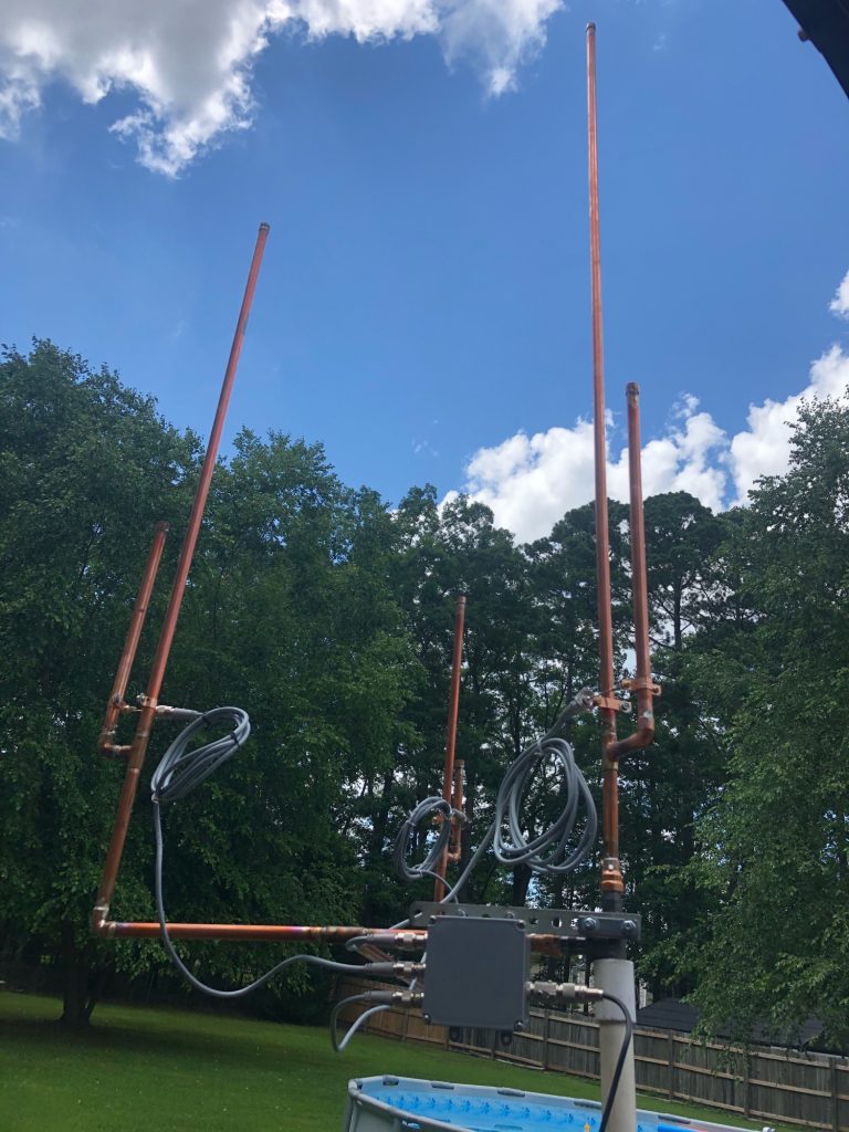
KO4DHJ’s Newly Built Triband 2m, 1.25m & 70cm Antenna
Newly licensed Ken, KO4DHJ has been busy! After some tuning the antennas will be ready to go on the roof.
Great job Ken!
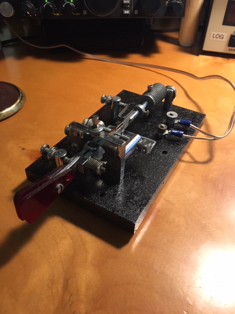
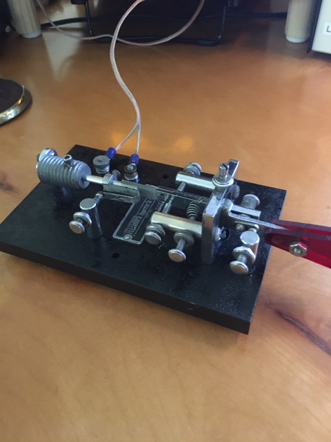
Bug Refurb – Another Piece from the Old Novice Station
from Bruce, N1LN
Another piece of the old novice station finished today. The bug is one that my long ago SK uncle, W2NAD, gave me after I first got my ticket. Since then I modified it into a paddle to use with a keyer I built from the ARRL book, Understanding Amateur Radio.
Now about 56 years later, it is a bug again!
[c] [y] photo by N1LN, OCRA Inc
I lost the original weights so I made one out of a large galvanized bolt. I cut the head off with a hack saw, drilled it / tapped it and DONE!
[c] [y] photo by N1LN, OCRA Inc
He also let me borrow his HQ-129X, which is why I purchased one to go with my DX60 / HG10 combo.
Quaradoodles from the Land of Magic
Wilson, W4BOH
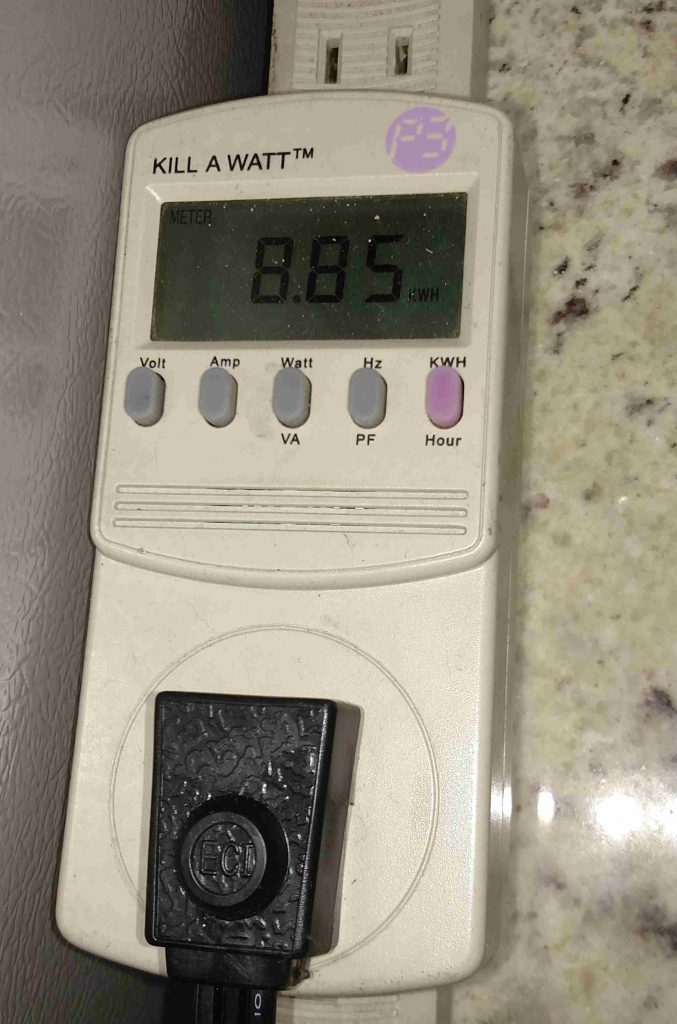
I’m really no less busy, but have used quarantine as an excuse to do a few fun things. Do you have a Kill-A-Watt, the great little $25 power meter. I do, but it’s been used almost entirely for measuring current drawn for various devices. But wait, there’s more! It does the obvious frequency, voltage, current measurements, but also POWER FACTOR (cosine of the phase angle between voltage and current). AND CUMULATIVE CONSUMPTION since last started.
[c] [y] photo by W4BOH, OCRA Inc
Here’s the tie to Covid: When I really think ahead, I can imagine power blackouts, short or long, leading to thoughts of generators to run things around the house. Of course there’s been lots of generator talk concerning Field Day too. So what’s my main concern about power? The weather is so nice that HVAC is not of interest. It’s too much load for to support for very long anyway. Next comes BEER! I like warm beer, but the same fridge also keeps our hamburger, bacon, etc., so it’s very important. Well, we just got a new fridge, a Frigidaire.
BTW, are you old enough to remember when lots of people called any fridge a Frigidaire? That’s the reward for being early to a big market. I don’t remember not having a fridge, but I vividly remember neighbors who didn’t and, most interesting, the old man who drove an old wagon, pulled by an old horse, through our neighborhood. Houses using ice had a little sign they hung by their front doors to tell the iceman how much to leave. He would carry the ice in and put it in your icebox, if you wanted. He had bags of coal too. We kids would go along and chat with the old guy and eat ice chips from the bed of the wagon. I don’t think there was a sanitation grade on the wagon.
The previous fridge was a Whirlpool, a mechanical mess and a power hog. Maybe they are better now, but I wouldn’t bother with them. Getting back on track now…. Would it be practical to run the new fridge from a generator and/or batteries? YES, since it runs at an incredible low current of ONE AMP, 120Watts! Now, that’s way low power for any generator (although the inverter models idle down pretty well) and the efficiency of gasoliine use would be poor. So what to do?
There are lots of inverters available these days and even real sine wave models are reasonably priced. I don’t know, but a 500W model would likely handle the 3A or so starting current of the Frigidaire. SO what does the Kill-A-Watt tell us, besides the one Amp running current? I ran a 100 hour test period, four days, during recent temperate weather, with the kitchen running around 70 degrees F most of the time. Over the 100 hours we used 5KWh, so the average load is 50 Watts and the running time was 40 hours. That’s about 1.2KWh/day, costing about $55/year around here. And how does that relate to batteries? It’s almost exactly the rated capacity of the big AGM batteries we got from Adriano last year, 120Ahr at 12VDC.
But you don’t want to run your batteries all the way down, so we can think of two batteries we recharge once a day.. The problem then is to choose a reasonable charge rate and charger. A conservative charge rate of C/6 would be 20A per battery or 40A needed from the charger. That’s only about 500W, still low, but better. The Honda 2200W generator claims to use 0.17 gal/hr at 1100 W. That’s 21,250 BTU from gasoline to make 1.1KWh or 3750BTU of electricity. An efficiency of 18%, gas in to electricity out, NOT SO GOOD. Let’s call it 15% at lower load. Making electric heat from gasoline is NOT a good thing! Assuming we can get 15% at 500W (wildly optimistic), we need 11350 BTU of gasoline to make our 1700 BTU (0.5KWh) of electricity. That’s about 0.1 gallon! It’s also about a beer can full.
That seems too good to be true, to me, but it’s what the numbers say, if Honda isn’t lying. It’s 20 cents, if gas is $2/gal and you’re getting about 6 cents worth of power, if you got it from the grid. That shows that you can’t beat the power company, unless you get some PV panels! And don’t forget, you’ll have to run like that for 5 hours to get your batteries back up, costing you about a buck. What ho, that’s $365 for a year, versus the $55 running on the grid, but your beer is cool and your steak doesn’t spoil!
And we neglected the $1000 for the generator and the $200 for the inverter, but we won’t charge for them, because we need them for Field Day!
Or you could run off the 12V battery in your Prius, but that recharge would be much less efficient.
Now, I did this quickly, for fun, so feel free to point out my errors. There’s some rounding and some assumptions, so we’re looking for 25% accuracy, at best. If I’m in that range, I’m happy, but I still worry about the Honda claim.
73,
WL
Great Time to Update the Hamshack
From Keith, W1KES
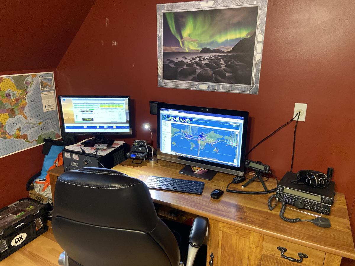
Last month, we repainted our bonus room, A.K.A. dad’s shack after 17 years. Additionally, we added new furniture and shelves. I have spent the last several weeks organizing and optimizing the space. My shack also serves as my home office, which has received more use this past week than the previous year. With kids out of school until mid-May, I plan to spend many hours working and “hamming” in my recently renovated space.
Before
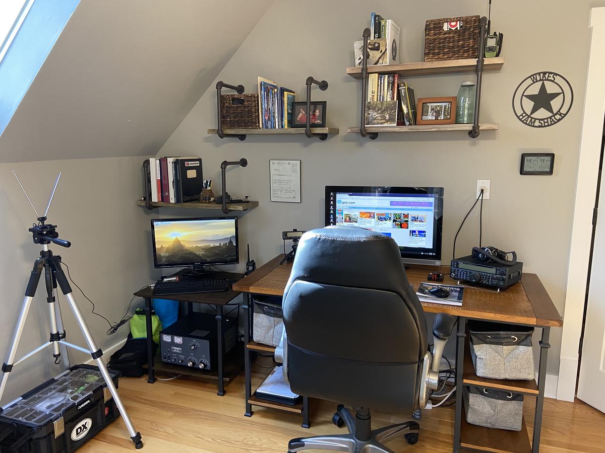
After
From the Land of Magic – Solar Panel Load Controller
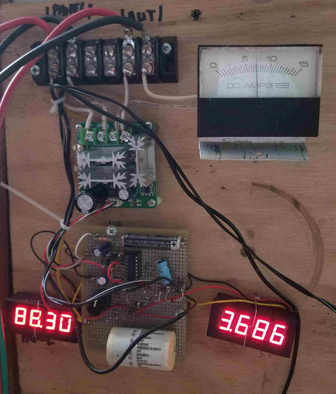
From the Land of Magic! a high tech solar panel load controller, built for son Pete. You can see that the latest components and construction methods are employed.
There’s a differential amp that drives an Ebay PWM speed controller ($11) to load the panels to their max power voltage, regardless of the insolaton* level. A sample of the panel voltage is compared to a Zener reference to generate the control signal to the PWM unit.The load is a 4500W water heater element in a tank in front of his regular water heater. There are three 235W panels with 29.4 V max power voltage.
I had a great talk with a dealer recently. It seems that PV power is now cheaper than heating water directly with wet panels. Cheaper panels and good inverters seem to have made a big difference.
Wilson, W4BOH
insolation* – No that’s not a mispillin’ Insolation‘ is the solar radiation (power/Unit Area) that reaches the earth’s surface, which average high sun is close to 1KW/square meter.
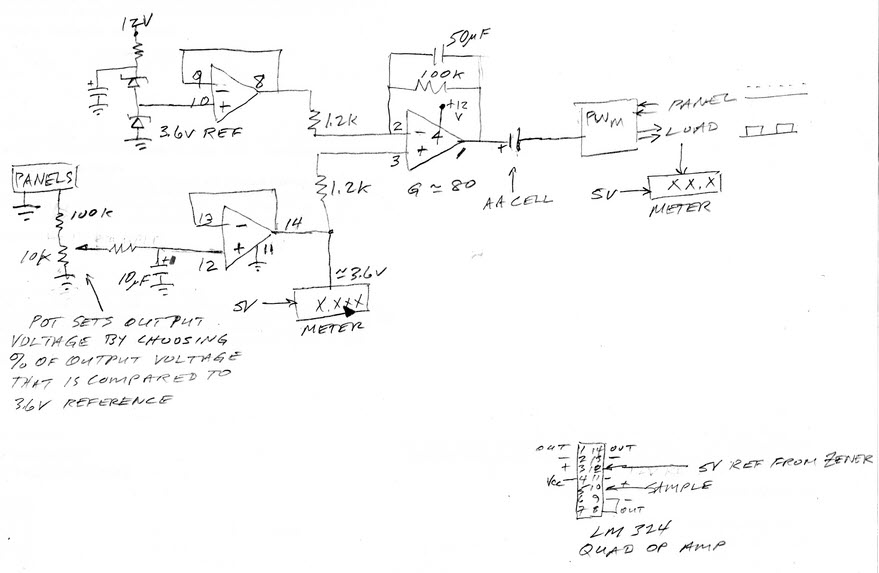
Controller Schematic
A Better Mouse Trap or is that a CW Key?
Well I’m quite familar snap! with the Victor mouse trap after a recent bout of mice invading the garage and building nice little nests in the heater air intakes of not just one but two cars.. little buggers!
But, Ken AC4RD’s use of said device plus a couple Fender guitar picks and a wine bottle cork brings a whole new meaning to home brew! Always thought those wine bottle corks had another great use.
Thanks, Ken!
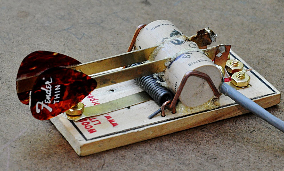
[c] [y] photo by Ken AC4RD, OCRA Inc
Sheltering in Place due to the Coronavirus?
and want to stay in touch with your ham friends?
Show your friends your latest pride and joy project or any field of interest you would like to share with your ham friends.
How? Send an email to orange.county.radio.amateurs@gmail.com with attached photos, or a link to the photos you wish to share, a brief description and I’ll post it on the OCRA website.
Face to face OCRA Club, Volunteer Exam Sessions & Board Meetings are cancelled until further notice due to the Coronavirus pandemic.
However, On-the-Air meetings and videoconferencing meetings will be used as an alternative. Stay “tuned” to OCRA-DFMA Joint Email List
Dan, KR4UB
What is it?
Well lets see… a large open field, complete with shadow of another tower with 2 large beams (and climber down below) A top-hat loaded 100′ tower for the 160m band that the owner plows in sixty-six 90 foot long radials for maximum performance.
Who else? Of course its the new N1LN 160m band antenna setup.
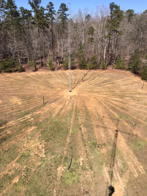
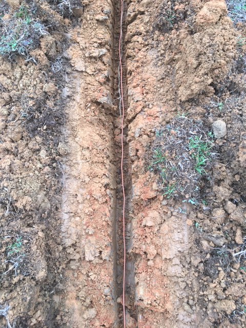
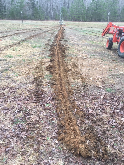
Kubota tractor with an attitude..

Polycomm (Obi) 202 as a shack telephone service solution
By Charles McComas KN4PTU
I like having a wired desk phone in my home office/radio shack for use during conference calls and long waits for tech support. The clarity and functionality of a landline desk phone is much better than the average cellular connection. Until the last few months this was handled quite well by a VPN connection to my employer’s Cisco VOIP system. After I retired, I started looking for a new solution. In a perfect world, I would have gotten a POTS (Plain Old Telephone Service) line, as the reliability of the old analog copper wire system is unmatched by the newer VOIP (Voice over Internet Protocol) telephone services. Unfortunately new POTS lines are not available and all telephone service providers are rapidly changing existing lines to VOIP.
Checking with AT&T, my current ISP (Internet Service Provider), it would cost me a $100 setup fee and around twenty dollars a month for a phone line. I have had great experiences with the knowledgeable AT&T technicians in the past but a $100 service call to plug in a patch cable is a bit steep.
In my net surfing I came across Obi, who makes a range of ATA (Analog Telephone Adaptors) devices and phones. I ordered an Obi, now Polycom Obi202 ATA (Photo 1) as it has a second phone line port that I plan to use for the fax function on my multi-function printer.
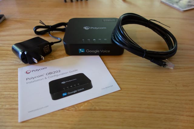
(Photo 1) Polycom Obi202
The back of the unit (Photo 2) has the two phone line (RJ11) connectors, a USB port for future functionality and two RJ45 connectors, one for Internet in and one for Internet out.
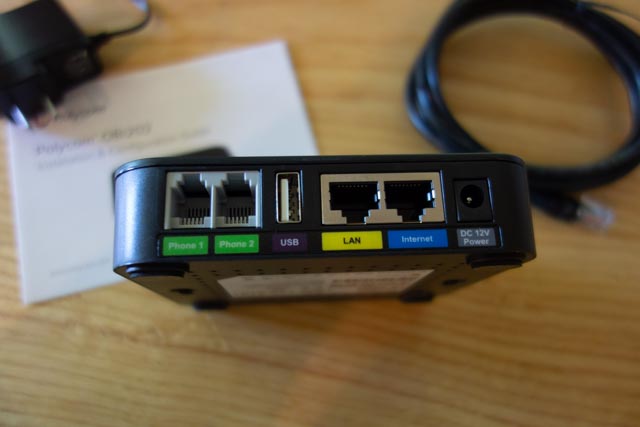
(Photo 2) Back of the unit.
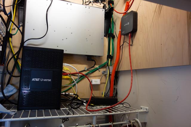
I will be installing the device in my hallway coat/telecom closet (Photo 3).
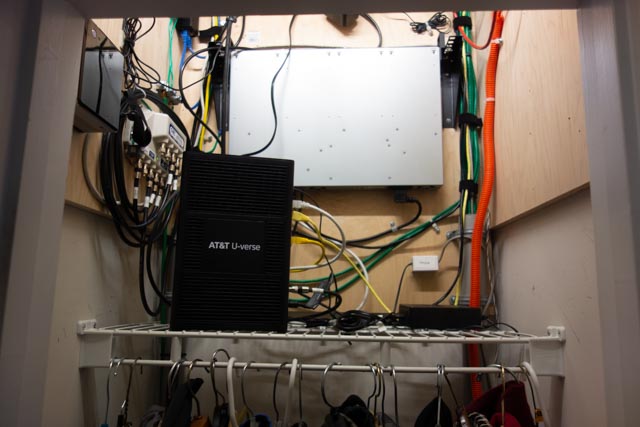
(Photo 3) Telecom closet.
I used a piece of masking tape to make a template for the mounting slots (Photo 4).
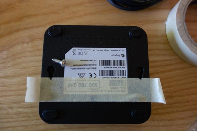
(Photo 4) Marking the mounting slots
I drew a level line with a torpedo level and stuck the tape to the line (Photo 5).
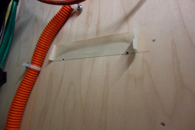
(Photo 5) Tape template and level line
Drilled the holes for the mounting screws (Provide your own) and screwed them in (Photo 6).
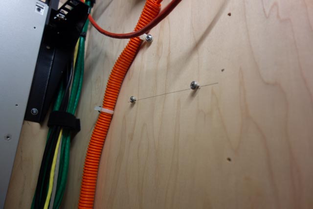
(Photo 6) Installed mounting screws
I connected the provided patch cable to an open Ethernet port on the AT&T modem (Photo 7).
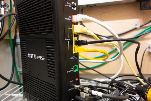
(Photo 7) Modem Ethernet ports.
and to the Internet in port on the device (Photo 8).
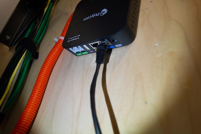
(Photo 8) Patch cable attached to the Obi 202
A four-wire phone cable with RJ11 connectors goes from the Phone 1 port on the unit to a surface mount block in the closet (Photo 9).
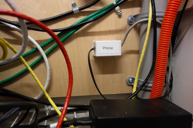
(Photo 9) Telephone line cable connected to the surface mount block.
. The cable from the block is spliced into the house’s original telephone service cabling and provides a dial tone to every telephone outlet in the house.
Before installing the power supply, I mark it with a paint marker to identify what equipment it is used for and the output voltage (Photo 10).
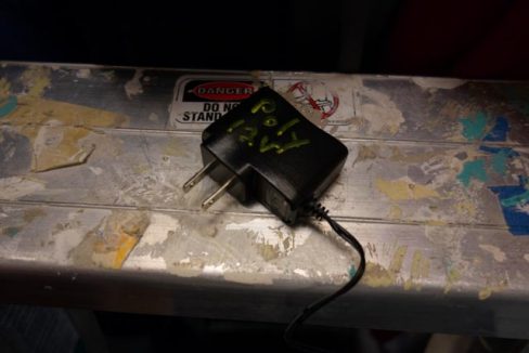
(Photo 10) Power supply
This comes in handy later to match up equipment with a power supply or to clean out a drawer that is overflowing with old power supplies.
The power supply is connected to an open outlet on the server rack PDU (Power Distribution Unit) and to the device. We have power and blinking lights (Photo 11).
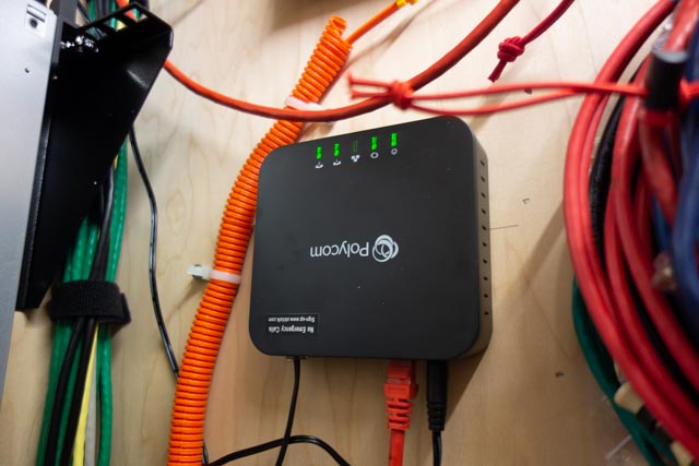
(Photo 10) Connected and powered up.
An Aastra 480e, analog desk phone, is connected to the phone jack in my office. I have a dial tone and I dial the special number provided in the instruction and do a echo test (Photo 11).
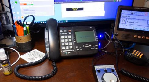
(Photo 11) Desk phone in place.
The next step is to set up a account on Obitalk.com. Once you have done that, you start the setup for a new device. On the phone connected to the ATA, you dial the number provided on the setup page and the Obitalk back end server identifies the device and you will see the device listed on your account web page
With a Obitalk account you can call and talk to other Obitalk accounts for free, but to call outside of the Obitalk network you need to have a account with a VOIP service provider. Obitalk supports most of the major home and small office VOIP providers as well as Google Voice. I have used Google Voice since before the technology was bought by Google and have been satisfied with the service. Best of all it is free for calls in the U.S. and Canada. But if you think that Google already knows too much about your life, you can go with one of the other VOIP providers. Also a big Warning, 9-1-1 service does not work with Google Voice. However you can add 9-1-1 service from another provider to your setup in Obitalk and still use Google Voice. Another concern is what Google gives for free, can be taken away in an instant, so I would not use a free Google Voice account for a phone number that is tightly tied to your business or where you can’t take an outage for a day or two. If you pay for G suite, those worries are about nil as Voice is part of G suite
Since I used my Google account to set up my Obitalk account, it had already configuring the Polycom Obi 202 to work with Google Voice. I made a few selections on what phone line to use for inbound and outbound calls and that was it. Configuration took less than 10 minutes and the total time I spent on the installation was about a hour. Most of that time was bringing in and then putting up the tools I used to install the device in my closet. Voice quality is very good. Reliability is too soon to tell.
(Photo 12) The finished installation
Bill, N8BR on the OCRA Monday Night 10M Net via Video Conference
Remember the HF phone patch that used to be commonplace in the ham shack years ago? How about a video conference HF patch? Or for that matter, flip a switch and it’s a video conference to VHF/UHF patch?
Bill, N8BR does not have an HF station at his QTH, but that did not stop him from listening to the net and Dan, KR4UB passing on his comments to the net.
Dan hosted a video conference and invited Bill to join the OCRA Monday Night 10M Net on 28.450 via video conference. Ham station audio is fed into the computer running the video conference application. A simple switch of the video conference microphone device driver setting from the normally used Logitech HD camera microphone to the computer line-input brings the ham radio receiver audio and Dan’s Heil headset microphone audio into the video conference.
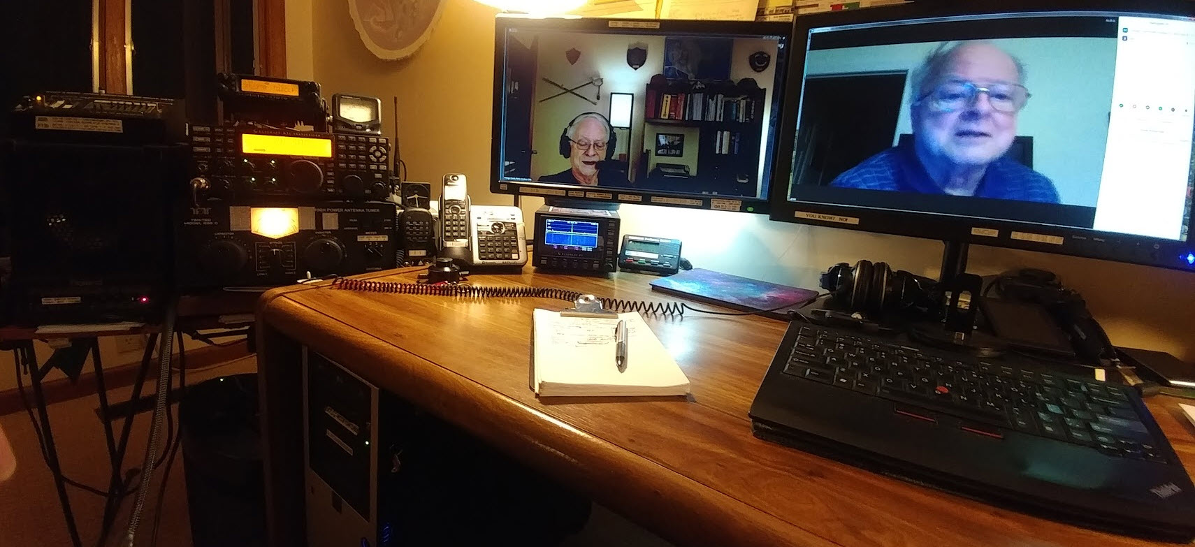
[c] [y] photo by KR4UB, OCRA Inc
Much of the equipment used and shown below has origin in other usage and has morphed into a small home audio studio serving multiple purposes. This application is a good example of the versatility it can provide.
The video conference “audio patch” application demonstrated here might could be built using some of the audio interfacing devices found in today’s ham shack for computer sound card driven amateur radio communication modes. However, if undertaken getting the audio chain correct might still require use of external audio mixers, attenuators, and additional isolation and perhaps impedance matching transformers, and instrumentation to get the sound right.
W2IHY Technologies Equalizer Function
The ham radio connections in this setup uses a W2IHY Technologies Equalizer that has multiple microphone inputs, one used for the Heil Headset microphone and a second input is used for the video conference inbound audio feed. The internal microphone amplifier gain is adjustable to ensure appropriate drive level to the selected ham transmitter with the output fed via an internal isolation transformer for RFI protection. The output is switch selectable to one of two ham station transmitters, in this case a Yaesu 8900 VHF/UHF and the Elecraft K3s transceiver. The phone jack output is an outbound (ham transmitter mic input) audio monitor output that is also connected to one of the Roland Monitors as described below. The equalizer interconnection ports available for all audio outbound to the ham radios are shown below.
Roland CM-30 Studio Monitor Function
Two Roland CM-30 Mini-Cube Studio Monitors in an interconnected stereo link configuration provides multiple audio channel mixer inputs as shown below on the one of the two units. One of the CM-30 units is used for all inbound (video conference incoming audio & ham radio receiver audio) feed mixing. Outbound (ham transmitter microphone inputs & video conference outbound) audio is separately mixed in, permitting audio from all sources to be monitored on the Heil headset as a final control operator quality check. Roland, a major manufacturer of musical instruments and sound stage equipment describes the CM-30 as a multi-purpose portable mixing monitor for the home-studio and portable live monitoring onstage applications.
A Jensen two channel isolation transformer previously used in a home theatre application is used to provide RF & ground loop isolation between the ham station and computer audio connections. Braid ground strapping bonds all equipment to the common station ground.
A recently added connection for the video conference audio output will permit that feed to be mixed into the Elecraft HF or the Yaesu VHF/UHF mic input so video conference folks have half-duplex two way audio communications and can join the rag chew. None of this will be automatic and will require the control operator to set up the “audio patch” and operate the PTT control, the same as was required by the FCC back in the days of “phone patch” operations.
Inbound, Outbound, Mixing, Attenuators, etc, etc
Does the above discussion of all the inbound, outbound, audio mixing sound like one giant circular loop? Not surprising… Ever wonder why speakerphones, telephone handsets, cellphones, bluetooth headsets, hearing aids and now video/audio conferencing…. any accoustic environment where speakers and microphones are in close audio proximity doesn’t turn into an enormous squealing audio feed back loop? You’ve probably heard that many times with public address systems. What’s the magic? What invention took place and has been deployed in telephone systems from the beginning? The telephone hybrid transformer, used in bidirectional audio paths where two audio directions are combined in to a single audio channel. This function is essential in today’s world of communication devices and typically done with digitial signal audio processing. The mixing and combining of audio paths described in the above setup had to be done in a way to avoid generating an audio feedback loop at several possible points in the circuit. The bidirectional processing or half-duplexing of conference audio by a video conference service is also a necessary ingredient.
The Nearby HT / Repeater Echo Effect
You’ve probably have experienced this effect in ham gatherings when you transmit on with your HT into a repeater and someone close to you has their HT volume turned up on the same repeater you are using. You’ll hear your own voice coming through being delayed in time or an outright audio feed back squeal occurring. The delayed audio echo effect is caused by an audio delay line in the repeater controller for the purpose of removing squelch noise bursts at the beginning and end of every transmission into the repeater and also for masking DTMF repeater control tones sent to the repeater. The OCRA 442.150mHz repeater is programmed to use a 70 msec audio delay to accomplish the above purposes. Sounds short, but very disorienting to hear your own voice delayed in time as you try to speak!
The conference to repeater audio bridge described in this article can have similar echos in the video conference side when repeater radio transmissions are recirculated from radios in the video conference. Video conferences can be more vulnerable as downloaded video conference applications typically provide a microphone audio AGC (automatic gain control) that if checked will adjust your computer/conference device microphone gain on the fly to make all voices at the same level in the conference. This is a good thing for the conference, but stray radio audio can be problematic.
However, the effect can be totally eliminated by proper audio protocols being practiced by those in the video conference. Those procedures will be described in a separate article.
While the equipment used here may border on overkill, hopefully the above audio discussion explains the necessity and there are advantages especially in the ability to measure, set and monitor audio levels at the key points in the audio chain. Among other uses, this setup has been used for some years as the final over the air audio level checks before a newly built repeater is deployed to a difficult to reach site such as the OCRA 442.150 mHz repeater located high up on the TV tower.
The setup is also used for periodic repeater checks and troubleshooting when repeater problems have arisen. The computer can do extended VOX triggered recording of the repeater to catch intermittent problems and spectrographic analysis software can be helpful on certain types of repeater issues.
Useful Software for Proper Audio Setup
Two computer applications were used to adjust the audio levels for optimum quality. The first program called Spectrogram, used in a vast range of fields, was written many years ago by Richard Horne, an Electrical Engineer working for the U.S. Navy. The second program Goldwave, a professional digital audio application was used to analyze historic recordings of the Moon landing, including establishing the “missing word” from astronaut Neil Armstrong’s famous line.
In summary, the building of this setup has been heavily influenced by other audio interests & needs, but also by experience in building the OCRA repeaters for the last 20 years. Mentoring by Danny, K4ITL in the early days of repeater building taught what it takes to set up repeaters to have excellent audio quality.
Dan, KR4UB
It was the night before Christmas and….
It was the night before Christmas and ….
Oh, No, No, No!!!!
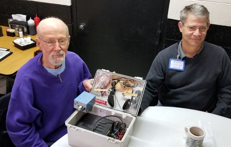
It was Saturday morning before Christmas, 2019, and seven local hams were gathered at the rear round table of Virlie’s Grill, Pittsboro, NC. Just the week before, John Mitchell, KK4VUR had distributed early Christmas gifts of nice surplus utility enclosures. BIG THANKS to John, KK4VUR !
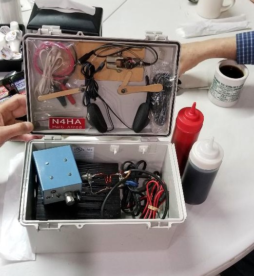
As part of the lively discussion this morning, Herb Allred, N4HA, revealed what he has already done with his utility box. Attached are photos of his “to go” station, with carrying handle attached to the top, containing his 20 meter CW QRP transceiver, antenna wire, iambic paddle, headphones and battery pack. The first photo shows Herb Alred, N4HA, on the left and Jim Davis, W4CFO, on the right. Note the use of popsicle sticks to secure the key paddle inside the lid of the box.
Very creative and ready to put on the air, maybe at a state park. Add a sandwich, drink and a few snacks in the box, (note the ketchup and maple syrup in the photo), and he is in for a good time.
Good luck Herb with many contacts and some DX. 20 meters has been better lately.
Don’t forget, Saturday mornings, 8:30 am (or earlier) at Virlie’s Grill, Pittsboro, NC (round table in the back of the room).
Best 73 and very MERRY CHRISTMAS to all and HAPPY NEW YEAR !
John, KX4P
Annual Ham Migration
While the crew at Virlie’s Grill took their annual vacation, the ham conclave met at the Root Cellar in Pittsboro for an enjoyableSaturday breakfast.
Pete, K4PHS, appeared wearing a tee shirt which advised us that there were “two types of people: 1) Those who extrapolate conclusions based on insufficient data.” (Some paraphrasing may have occurred.)
Bill, N8BR, is now selling his supply of RG400 coax in 10 foot lots. Cheap.
Terry, KK4JGT, our Chatham CERT organizer, announced a request for CERT support for a Haw River rescue exercise. He now has over a hundred on his mailing list and there are 21 hams.
Hank, K3YDX, participated in Field Day with a Snow Camp group. Casual and fun.
Herb, N4HA, enjoyed a 20 meter CW stint with the DFMA/OCRA team at W4EZ. Thanks to them.
John, KX4P, worked the Baker dxpedition on 40 meters 11 minutes before they closed up shop. That’s cutting it close, John.
SHOW & TELL TIME! John, KK4VUR, brought his newly constructed antenna amplifier for his satellite work. He added a T-bias to supply power. Does anyone remember what the Lagrangian point is? 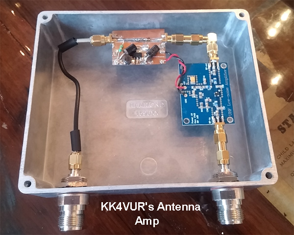
Nick, KA1HPM, brought his duplexer on which he repaired a broken coax center conductor with some electronic brain surgery. 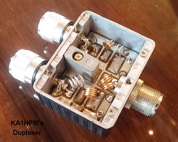
Hope you will join us and add your ham radio input to our next Saturday breakfast at Virlie’s Grill in Pittsboro. Photos by John, KX4P.
73, Herb, N4HA
Share Your Shack!
Keith, W1KES, shack. Please share pictures from where you like to operate!
Herb, N4HA wins Third Prize in the ARRL 2017 Antenna Design Competition for his 20M Two-Element Wire “IV” Beam
A week ago, at the Pittsboro Virlie’s Grill ham’s breakfast, Herb Allred, N4HA, mentioned he had entered an antenna design competition and been awarded 3rd place. We all congratulated him.
Nick, KA1HPM, found Herb’s name in the latest issue of QST. What he discovered was that Herb had placed 3rd in the 2017 ARRL Antenna Design Competition for “80 through 10 Meter” antennas ! His design was for “A 20-Meter Two-Element Wire ‘IV’ Beam.”
See QST, November 2017, page 45.
This is a significant accomplishment with a cash award and possibility of publication !
Congratulation Herb!