Great Time to Update the Hamshack

From Keith, W1KES

Last month, we repainted our bonus room, A.K.A. dad’s shack after 17 years. Additionally, we added new furniture and shelves. I have spent the last several weeks organizing and optimizing the space. My shack also serves as my home office, which has received more use this past week than the previous year. With kids out of school until mid-May, I plan to spend many hours working and “hamming” in my recently renovated space.

Before

After


From the Land of Magic – Solar Panel Load Controller

From the Land of Magic! a high tech solar panel load controller, built for son Pete. You can see that the latest components and construction methods are employed.

There’s a differential amp that drives an Ebay PWM speed controller ($11) to load the panels to their max power voltage, regardless of the insolaton* level. A sample of the panel voltage is compared to a Zener reference to generate the control signal to the PWM unit.The load is a 4500W water heater element in a tank in front of his regular water heater. There are three 235W panels with 29.4 V max power voltage.

I had a great talk with a dealer recently. It seems that PV power is now cheaper than heating water directly with wet panels. Cheaper panels and good inverters seem to have made a big difference.

Wilson, W4BOH

insolation* No that’s not a mispillin’  Insolation‘ is the solar radiation (power/Unit Area) that reaches the earth’s surface, which average high sun is close to 1KW/square meter.

Controller Schematic

A Better Mouse Trap or is that a CW Key?

Well I’m quite familar snap! with the Victor mouse trap after a recent bout of mice invading the garage and building nice little nests in the heater air intakes of not just one but two cars.. little buggers!

But, Ken AC4RD’s use of said device plus a couple Fender guitar picks and a wine bottle cork brings a whole new meaning to home brew! Always thought those wine bottle corks had another great use.

Thanks, Ken!

© 2024 photo by Ken AC4RD, OCRA Inc

Sheltering in Place due to the Coronavirus?

and want to stay in touch with your ham friends?

Show your friends your latest pride and joy project or any field of interest you would like to share with your ham friends.

How? Send an email to orange.county.radio.amateurs@gmail.com with attached photos, or a link to the photos you wish to share,  a brief description and I’ll post it on the OCRA website.

Face to face OCRA Club, Volunteer Exam Sessions & Board Meetings are cancelled until further notice due to the Coronavirus pandemic.

However, On-the-Air meetings and videoconferencing meetings will be used as an alternative. Stay “tuned” to OCRA-DFMA Joint Email List

Dan, KR4UB

What is it?

Well lets see… a large open field, complete with shadow of another tower with 2 large beams (and climber down below)  A top-hat loaded 100′ tower for the 160m band that the owner plows in sixty-six 90 foot long radials for maximum performance.

Who else? Of course its the new N1LN 160m band antenna setup.

Kubota tractor with an attitude..

Plan to use an Inverter Generator or run your Field Day station from a generator?

Variable speed inverter based generators offer significant reduction in audible noise and fuel consumption. Most consumer quality, constant speed generators that typically run at 3600 rpm are noisy and consume much more fuel.

  • The small inverter generators are well suited for Field Day due to their lower acoustic noise profile, provided their AC output is filtered to eliminate RF noise typically occuring in the 80m band.
  • Using short AC cords with no filter on an inverter based generator still presents unacceptable noise on 80M.
  • With no filter, detectable noise on the 40m through 10m bands was not found with the Honda generator shown in the next article below.
  • The RF noise filter in the next article using 3 large 4″ OD Fair-rite mix 31 toroid cores has been proven in a series of EMI test configurations to be effective in eliminating inverter generator noise. The complete, enclosed filter including a GFCI outlet with in-use rated cover for outdoor use, costs around $150 to build.

The degree of interferenence to an 80m station from an inverter based generator & attached cord radiated RF noise coupling into the Field Day antenna will vary somewhat based on the station physical arrangement. The graphs below are the received signal into an 80M station antenna located up 55 feet in the air, with a 50 foot drop cord lying on the ground underneath a portion of the antenna that connects the generator to the load.

noise profile

© 2024 photo by KR4UB, OCRA Inc

Thinking about running your Field Day station directly off a generator and not using batteries?

There has been discussion of eliminating batteries all together (as the Field Day rules permit) and run the station on a small generator. Tests should be done before Field Day with the specific AC to DC power supply and generator to be used to determine if the fluctuating loads of a CW/SSB transmitter is going to cause deep fluctuations in generator engine speed.

Why would one care?  Most hams know that with synchronous (aka constant speed) generators the frequency output is determined by the speed the armature is rotating, and the number of poles in the armature.  What may not be known is that the raw voltage output of the generator winding varies proportionally with speed at which it passes through the magnetic field (aka armature rpm). That’s why all synchronous generators have a voltage regulator circuit that adjusts the other variable affecting voltage output, the strength of the magnetic field.  The question is how well in a consumer quality generator does the voltage regulator and, the mechanical engine speed governor handle wild fluctuations in electrical load.

Rather than using mechnical speed governors, commercial large scale generators use electronic throttle control systems for more precise control of engine speed by comparing generator output frequency to the throttle controller’s internal 60Hz frequency standard.

Rather than expose expensive radios and DC power supplies to such effects,  one fix could be to still use a battery or two in the 12VDC circuit to buffer the generator from the wildly fluctuating loads such as a CW transmitter.

A Power Line Filter for an Inverter Generator

Dan, KR4UB

After viewing a recent Youtube video posted by the American Radio Relay League, Inc ARRL youtube video regarding RF noise that can be generated by inverter based generators, I decided to do some testing of my inverter generator, a later model, slightly higher capacity unit compared to a Honda generator in the ARRL youtube video.

First Impressions

The RF noise characteristics of my eu2200i unit do not seem as pronounced as demonstrated in the ARRL video, although that could be due to test configuration differences. It was noticed in the video that their antenna was very low and close to the generators. The horizontal loop and dipole antennas at home used in this testing are at an approximate 55 foot height over the test area.

  • The only amateur band that had generator noise was 80 meters and was loud enough to be an issue for Field Day.
  • Reducing the generator load helps reduce radiated RF noise.
  • Using a shorter drop cord can help, but not enough to eliminate generator inverter radiated noise.

Line Filter Project

Given the club’s Field Day plans to run in a higher RF power output class with the associated higher battery draw, the two transmitters of the combined 10m/6m stations I help set up and operate will be especially demanding on the batteries. If the Honda inverter generator is to be used to recharge this station’s batteries, a fix is needed to eliminate the possibility of RF interference to nearby field day stations.

The first step of the project began with a conversation with Howie, WA4PSC ProAudio Engineering who stocks the Fair-Rite toroid cores, regarding the best choice of ferrite toroids. His recommendation was the Fair-Rite 4.0” OD x 1″ H mix 31 units, given the frequency range at issue and will permit larger spacing between turns for less capacitive coupling.

The test configuration consists of the Honda inverter generator, drop cord and the power load placed beneath my HF horizontal loop antenna located approximately 55’ overhead. It was also in the vicinity of a dipole antenna also at 55’ above ground. Noise was observed on an Elecraft K3s and a SDRPlay 1a SDR receiver both using the same antenna. All displays of received noise below are from the SDRPlay 1a SDRuno application.

The generator test load is a 1500 watt electric heater, connected to the generator by a 50’ long drop cord. Several orientations of the drop cord were tried and as expected, there is an observable difference in received radiated noise based on drop cord orientation.

© 2024 photo by KR4UB, OCRA Inc

Two filter configurations were tested using different toroid winding configurations, both using three of the Fair-Rite 4″ OD x 3″ ID x 1″ L 2631814002 toroids.

Toroid Configuration #1

Not knowing whether the preponderance of the Honda inverter generator noise was common mode or differential mode, the first test was with toroid #1 wound with both neutral and the hot lead in a common mode attenuation configuration and then toroids #2 & #3 used as follows. Toroid #2 was for neutral & ground, wound for differential mode attenuation and toroid #3 for the hot lead similarly wound for differential mode attenuation. This configuration was not very effective in reducing the observed noise.

Toroid Configuration #2

Not satisfied with the above result, the toroids were all rewound for common mode attenuation as shown below:

The hot and neutral lines are wound on two toroids “in series” and the ground wire which can also be driven by common mode noise is on a separate toroid.

The “missing” (or more widely spaced turns you see in the photo below (at the top & bottom of each toroid) were required for these 4″ OD toroids to fit in the 4″ deep box and permit the cover to go back on. As shown the larger 4” OD toroids permit wider spacing between the turns and thus reduce capacitive through coupling across the turns.

© 2024 photo by KR4UB, OCRA Inc

One detail on the unfinished design above will be to bring out a ground wire stud for connection to a ground rod to be located near the generator.

RF Noise Test Results

Using a real world 80m antenna as the test reference for radiated RF generator noise is not ideal in determining any absolute noise level reduction by the filter given the typical high 80M noise floor. But it does reflect the real world of a typical Field Day station setup.

The unfiltered RF noise of the generator driving a 1500 watt load via a 50’ drop cord is shown below in the bandscope display of my SDR receiver connected to the horizontal loop antenna. The display shows the frequencies (the repeating blue bands) and correlating waves of increased noise across the noise floor of the 80m band. Using AM detector mode, the noise is audibly loud; however in LSB detection mode the noise is not audibly loud, just a higher background impulse type sound. While there were some signals on the band, only one (the orange line) was strong enough to show above the elevated noise floor.

© 2024 photo by KR4UB, OCRA Inc

Below is a sweep of the ambient 80m noise level without the generator running and, ironically during a widespread AC power outage that occurred February 07, 2020. The amateur radio station is powered directly by a large battery bank and the computer for this testing is on a high quality (and very low generated noise) UPS designed for the commercial market sector.

© 2024 photo by KR4UB, OCRA Inc

To illustrate the effect of generator load or lack of, on radiated noise, the 80m radiated noise shown below is with the same configuration as the first chart, i.e. the 50 foot cord attached, no filter, and no electrical load on the generator.

© 2024 photo by KR4UB, OCRA Inc

Finally, the noise filter effectiveness of Toroid Configuration #2 is shown below. The measurement below is with the same 1500 watt load, connected through the 50 foot drop cord, but with the filter inserted at the generator as shown on the next page. Compared to the first chart with no filtering, none of the repeating blue bands and correlating waves of increased noise are present across the 80m spectrum. No interference was found on the 40m – 10m ham bands or adjacent frequency bands. The multi colored traces are 80m stations active during the measurement.

© 2024 photo by KR4UB, OCRA Inc

Throughout the test, care was taken to keep all connected equipment and the drop cord in the same physical configuration. Earlier testing showed drop cord orientation (and of course length) can make a considerable difference in results.

Filter at the grounded generator & 50 foot cord connecting the 1500 watt load

© 2024 photo by KR4UB, OCRA Inc

Final filter design

Below is the final design using toroid configuration #2, with a GFCI outlet and stud bolt connection for ground included. The stud bolt ground is connected to the GFCI electrical outlet ground and goes to the generator electrical outlet via the plug connected cable green wire. Per Honda documentation the outlet ground is internally connected to the generator frame components.

© 2024 photo by KR4UB, OCRA Inc

While test results show this filter to provide effective RF noise reduction with the Honda eu2200i inverter generator, other similar style inverter generators may present a different situation due to possible different power transistor technology and inverter switching rise times.

PostScript
A postscript is an afterthought, thought of occurring after the letter has been written and signed.
In discussing this filter with a few folks the conversation tends to turn to why this or why not that. The first EMI solution that works may be expensive and may not be the only design solution. Such is the world of EMI. The filter I built works, but with the included GFCI and other parts, is a bit pricey, approaching $140.00.  Would the smaller less expensive 2.4″ OD ferrites do the job? Testing of a filter using 3 of the 2.4″ OD cores proved the smaller cores to be ineffective. This is most likely from capacitive coupling of the closer wire turn spacing forced by the smaller diameter cores, or perhaps the core cross sectional area yields a magnetic flux path just too small for the amount of RF energy to be absorbed at the lower HF frequencies. Perhaps using only two 4″ OD toroids (eliminating the separate green wire ground toroid) might work, but hasn’t been tested.

Time spent learning what others have learned is always a worthwhile endeavor. Howie, WA4PSC of  ProAudio Engineering also passed on some excellent references for further reading. Jim Brown K9YC’s 60 years in ham radio, vice chair of AES Standards Committee working group on EMC and extensive research in the pro audio world is an excellent reference source. Jim’s  59 page “summary” reference document is well worth spending the time on the details of rf filter design. The filter design in this article correllates well with information his document regarding filters for the lower HF bands; e.g.two cores “in series”… check! … seven or more turns per mix 31 core… check! and choking the green wire ground… check, no out of sequence turns on the core… check!  Jim’s other publications can be found here.

46 SDR frequency sweeps, involving a number of test configurations, variation in filter components & design and involving considerable time were performed on this project looking for a better magic bullet. It did confirm the filter design in this article performed superbly over a number of test configurations, but no magic bullets were found.

It was the night before Christmas and….

It was the night before Christmas and ….

Oh, No, No, No!!!!

It was Saturday morning before Christmas, 2019, and seven local hams were gathered at the rear round table of Virlie’s Grill, Pittsboro, NC. Just the week before, John Mitchell, KK4VUR had distributed early Christmas gifts of nice surplus utility enclosures. BIG THANKS to John, KK4VUR !

As part of the lively discussion this morning, Herb Allred, N4HA, revealed what he has already done with his utility box. Attached are photos of his “to go” station, with carrying handle attached to the top, containing his 20 meter CW QRP transceiver, antenna wire, iambic paddle, headphones and battery pack. The first photo shows Herb Alred, N4HA, on the left and Jim Davis, W4CFO, on the right. Note the use of popsicle sticks to secure the key paddle inside the lid of the box.

Very creative and ready to put on the air, maybe at a state park. Add a sandwich, drink and a few snacks in the box, (note the ketchup and maple syrup in the photo), and he is in for a good time.

Good luck Herb with many contacts and some DX. 20 meters has been better lately.

Don’t forget, Saturday mornings, 8:30 am (or earlier) at Virlie’s Grill, Pittsboro, NC (round table in the back of the room).

Best 73 and very MERRY CHRISTMAS to all and HAPPY NEW YEAR !

John, KX4P

Morse Code Classes via a UHF Repeater… starting January 8th

Steve Jackson, KZ1X

revised December 29 2019 ….

The way that most people learn Morse Code best is in a classroom style setting. From roughly 1840 through about 1970, this was the manner in which most people learned Morse Code.

For a variety of reasons, beginning in the early 1980s, a trend began where people either did not have the opportunity to attend a classroom setting and / or took it upon themselves to try and self-teach the skill. The former is unfortunate; the latter, many times more challenging.

Well, amateur radio certainly has changed in the ensuing decades but what has not changed is the desire among many hams to be able to use Morse Code on the air.

Due to practical limitations such as the lack of a suitable classroom venue, the geographically diverse nature of potential students, busy lifestyles, and availability of instructors, it is not likely we will see a return to regularly scheduled, local, sit-down type Morse Code classes.

However, for those who do wish to learn in a class-styled environment, and who already hold a Technician or higher grade of amateur license, there may still be an alternative for a group-oriented Morse Code learning environment.

A Proposal

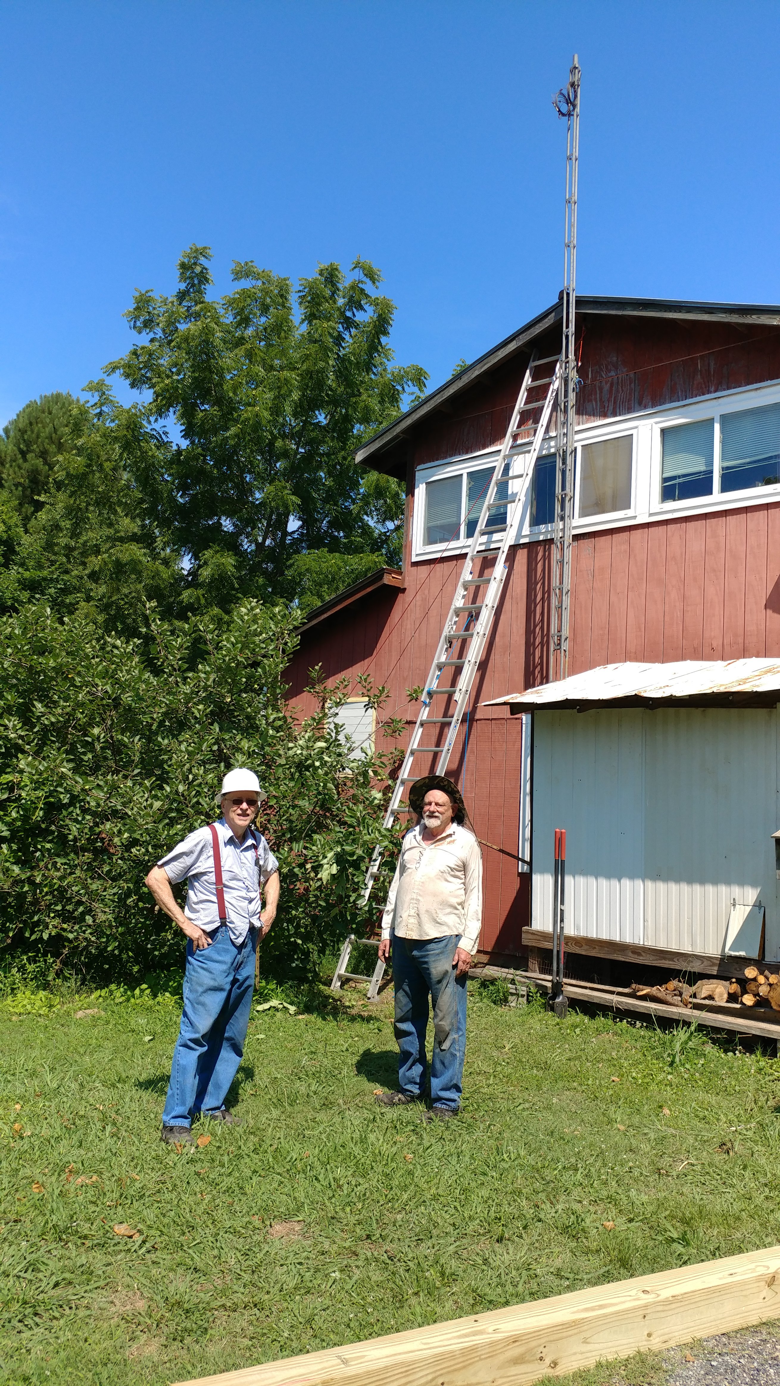
OCRA maintains a wide coverage UHF repeater. Like the majority of repeaters over the past 15 years or so, it is inactive most of the time.

This terrific and underutilized resource could easily host a scheduled on-the-air Morse Code class for students already holding amateur licenses. This document describes such a class.

Conceptually, the idea is simply to move a traditional sit-down classroom experience to one conducted in real time via a repeater. By making it interactive, on the repeater, the class will train participants to communicate over-the-air in Morse Code.

Yes, that’s it. The sole goal of the class is conferring the demonstrable ability to send and receive Morse Code on the air.

Before you ask:

There is no sending or receiving speed goal for this class.

Setting such a goal was important in an era when there was a standardized FCC test to pass. Teaching to receive at a given speed did not serve students well; it only helped the test proctors. Moreover, without a sending test, the underlying Morse communications skill of the student is not certain.

Therefore, a fixed-speed goal is not appropriate for a Morse Code class taught in 2020. Think of this class instead like “Marconi meets Montessori.”

Anticipating your next question:

What speed are the lessons sent at?

The answer is:

Since the class goal is to be able to make practical use of Morse Code on the air, the so-called speed for lessons is actually a more complicated issue than a simple number.

The speed of the dots and dashes for lessons is set at the natural rhythm rate, such the listening part of the brain will not try to ‘count’ these symbols. Instead, each letter’s acoustic pattern gets interpreted by the brain as a unique musical sound. Thus, the same part of the brain used to remember the first notes of a favorite song is activated to memorize the letters.

This is also why significant effort has been put into making the tones used in the class have musical integrity (pitch, tonality, and harmonic content are controlled).

In turn, the space between the letters is artificially lengthened from the expected spacing, so that the student will have time to write down each letter sent.

Focusing on “how fast?” as the sole metric for success is great for horses, not for people. This is about recognition, not rate. Once one knows all the letters and digits, increased speed is then only a function of experience and desire.

How Will The Class Work?

A class participant will learn Morse code over a period of approximately two months. The letters of the alphabet, the ten digits, and certain punctuation and procedural signals are introduced to students each week, in a graduated process.

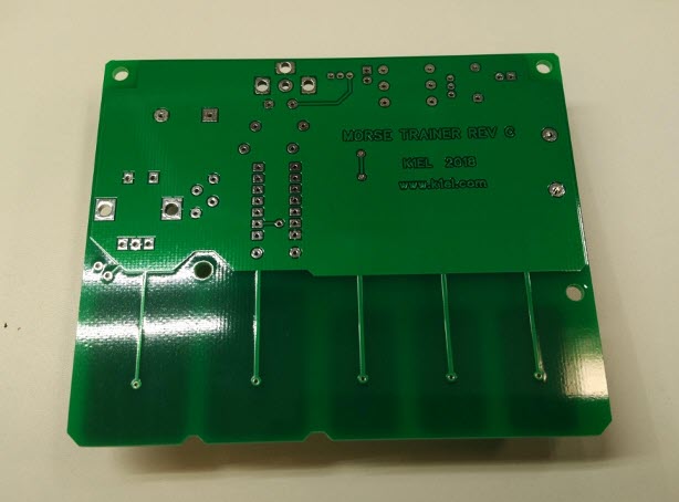
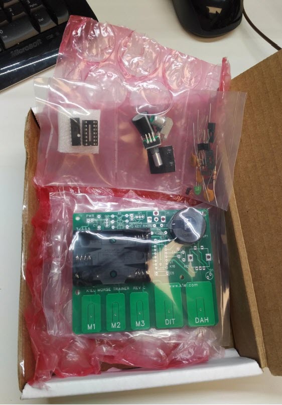
Materials used are a combination of a Windows software application by G4FON, the K1EL Morse Tutor keyer kits, and a weekly over-the-air interactive instructor-led lesson. The software is used to make the letter introductions, and to help weekly home practice.

Dividing the 26 letters into four groups allows one to learn the more frequently used letters first. In turn, this allows the most rapid progress towards forming words. Quickly thereafter, students can create simple sentences.

The class design is interactive because student participants both receive and send in each class, and draw upon each other’s success. All of this occurs exactly as it would in a ‘live’ in-person setting. It is therefore vitally important that the students faithfully complete each week’s homework and come prepared for the next class.

Classes, Equipment, and Software

Classes

The class itself consists of eight on-the-air lessons,  plus preparatory work.

Preparatory work consists of using the software to practice and learn the assigned new letters each week. Most people find that this will take from 1 to 3 hours per week. (Weeks 2 and 4 are hardest.)

Each on-the-air lesson will be roughly 30-45 minutes in length.

There is a fixed curriculum. One cannot ‘skip’ any lesson, nor are there any make-up lessons possible.

This is in part because the lessons are not simply recordings. They are interactive, and, each lesson builds upon the previous one. In addition, students are active participants in the learning process for and with other members of their cohort.

Each over-the-air lesson consists of a student-listening portion, and a student-sending portion.

  • In the student-listening portion of each class, the instructor reviews the new letters introduced the previous week, by sending the letters over the air to the students.

This listening portion consists of these most recent letters, sent in three sequences of ten random groups of four letters each. The instructor, using an automated tool, transmits these.

After the lesson, the actual letter groups sent will be posted on line, so students can check their copy.

  • In the student-sending portion, the student will formulate words from all the letters learned so far in the class, and then send those words over the air so other class participants can copy them. Each student will send at least two words (generally 4 or 5 letters each).

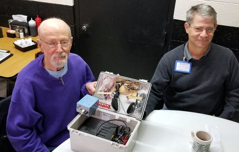
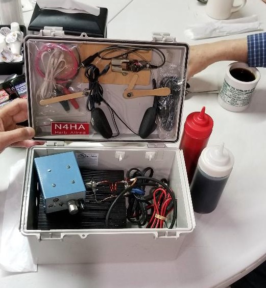
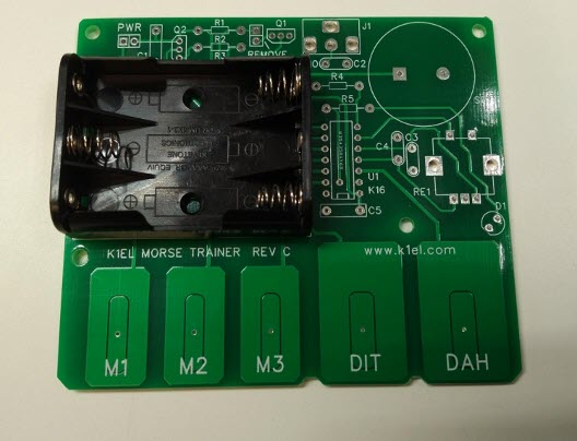
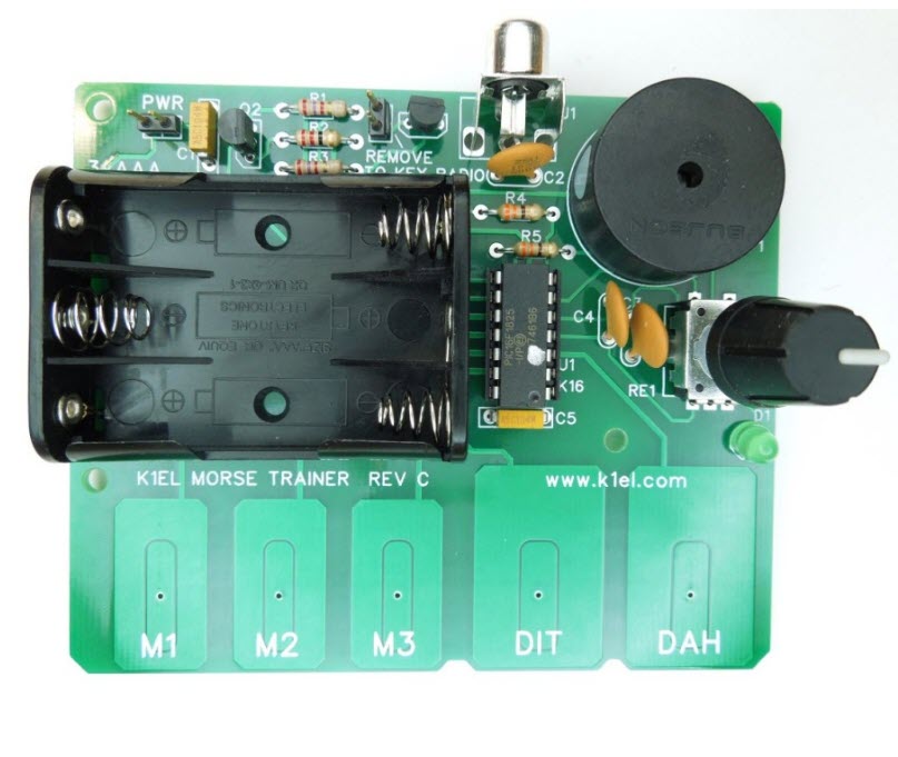
The student-sending portion of the class is one reason for the K1EL Morse Code tutor kits. These kits allow a low-cost way of sending good quality modulated-CW signals over the repeater.

If a student wishes to use some other Morse tone generation gear, that is their option. However, it will still be necessary to use the same settings as shown below (in the software topic), so that all class participants’ signals sound similar (pitch, speed, spacing).

The student will need to be able to hold their microphone close enough to their kit’s speaker so they can send their words over the air. Of course – they must ALSO access the repeater well while doing so.

Equipment

The intention is for the typical local, licensed amateur to participate in the class easily, with minimal additional expense.

An assumption is that all students will already have the means to access the repeater, often via a handheld radio. It is prudent to check one’s signal into the repeater from the location where one will participate in each week’s lesson, prior to starting the course. Adding an external gain antenna and perhaps a corded microphone accessory could be very helpful.

An in-person set-up session prior to the first class will be available, so that students’ K1EL Morse Tutor kits can be programmed. The reason for this is because the Morse Tutor kits are programmed using Morse Code, and of course, the student using this Tutor does not yet know Morse Code.

The programming will be for rates, student callsign, audio pitch, and related settings.

Software

The software used for the class is by G4FON. It is a Windows program. (If you absolutely must use some other platform, please contact Steve, KZ1X, to discuss options.)

Several features of this software make it the ideal choice. The primary one is the feature where the user can select specific letters for the computer to send, repeatedly, allowing the student to learn new letters every week according to the class syllabus.

Other G4FON program options allow the computer-generated Morse Code to ‘sound’ like the class lessons do.

To set up the G4FON software for the class, choose the following settings on the main screen:

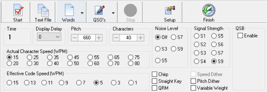
  • Set the Pitch to 660
  • Actual Character Speed to 15
  • Effective Code Speed to 5

and make any needed changes to the ‘button’ type options, as shown above.

Afterwards, open the ‘Setup’ tool and choose the “Morse Character Setup” tab:

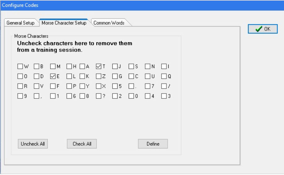
For the first lesson, choose only the letters ‘T’ and ‘E’ as shown above.

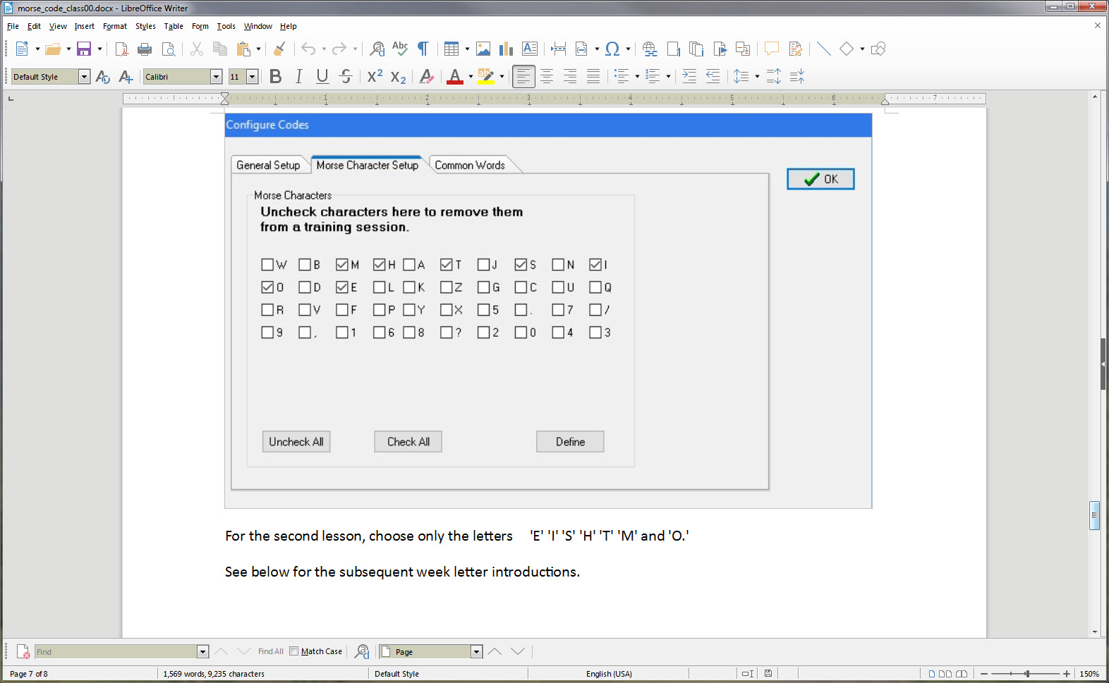
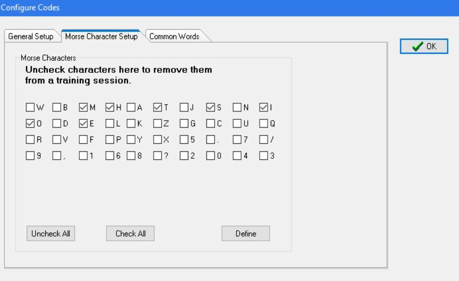
For the second lesson, choose only the letters ‘E’ ‘I’ ‘S’ ‘H’ ‘T’ ‘M’ and ‘O.’

See below for the subsequent week letter introductions.

Here is a link to access the software:

http://www.g4fon.net/CW%20Trainer.htm

Lessons

Lesson 1 E T

Lesson 2 E I S H T M O

Lesson 3 A W J N D B

Lesson 4 U V G Z K R P X

Lesson 5 F C L Q Y

Lesson 6 1 2 3 4 5

Lesson 7 6 7 8 9 0

Lesson 8 . , ? /

Morse Trainer Kit Build; What Happened, and What’s Next?

by Steve, KZ1X

At the OCRA meeting (14 Oct 2019) there was a group build session for assembling the K1EL Morse Tutor kit club project.

Of the 25 or so kits involved in the project, approximately 6 were completed prior to the meeting! Those are our eager builders, and we’re lucky to have folks like that here to learn from. So few areas have such a rich experienced resource these days.

Another approximately 13 kits were assembled at the event.

More than a few assemblers were first-time kit builders, so, they get a special shout-out, as do the several experienced mentors present whose help was invaluable.

Since the success rate for the kits was effectively 100%, we can move to discussion of an evaluation of the event, and some next steps.

To start … It did seem like the participants were fully engaged and either re-learning their assembly skills, or experiencing them for the first time. This is certainly a good thing!

It would be great to get some additional and candid feedback on what went well – and what could be improved for some possible future event like this. Please feel free to share here or via direct email.

Now that many people have these kits built and operating, what comes next?

Several things, in fact, come next.

Immediately, please try and familiarize yourself with the settings on the Morse Trainer units you built. Pay particular attention to the setting that lets you control the sound pitch (tone) of the sending. You will want/need to be able to change this.

Also, work on learning TO CLEARLY SEND the first four letters of the lessons: E, T, A and N. Don’t worry about speed, it’s the smoothness that’s important to get down pat.

If you need to hear what these letters should sound like, I will be ‘playing’ them on the air, just after the ARES nets on Saturday mornings.

Lastly, don’t forget to remove the power jumper on your Morse Tutor when not in use, since the battery will drain if left on. That would take a month or two, but, no sense in running the batteries down for no reason. Simply unplug the jumper from the two pins and then re-seat it on just one, so you won’t lose it.

After that …

    1. The intent has been all along to offer weekly Morse tutoring lessons over-the-air via the 442.150 repeater … and in fact these were originally intended to start around now. There have been several setbacks to this plan, delaying the rollout by multiple weeks. I ask forbearance, all successful ventures take more time than originally anticipated.
    2. Group study events … did anyone notice the special feature of this kit, which allows people to pair-off and send Morse to each other in small group settings? The kits have a common RCA type jack on them, and with a simple phono male-male cable (which the club has several of if you don’t) they can be connected directly together! The MOST productive way to learn Morse is to first master a handful of characters (that is the purpose of the over-the-air sessions), make up words using just those letters, then send the code to a partner for practice. Then, reverse the listener and sender. These study events can be as few as two people, or up to MANY, and should take about 20 minutes each. The only catch is that there needs to be someplace people can go and have a quiet place for the study session. We’re spread over a very wide geographic area so this becomes challenging to manage. In an ideal world, we’d all have a weekly lesson session, and nobody would miss one. More realistically, those sincerely interested in learning the code can work with a buddy, perhaps one closer by than further, and help each other out getting to learn all 26 letters, ten digits, and a few punctuation and prosign characters.
    3. Computer aided training … there is Morse tutorial available called G4FON (the call sign UK ham who originally came up with it) and it’s available for PC, Mac, tablets, phones, you name it.In the next week or two I will send more information about this software and how to set it up to complement the coming training sessions.

For now… here are some links, see if you can install this software in your favorite device, and please report all successes or any gotchas:

http://www.g4fon.net/CW%20Trainer.htm for Windows
https://apps.apple.com/us/app/morse-elmer/id414371107 Apple iOS
https://play.google.com/store/apps/details?id=net.iz2uuf.cwkoch&hl=en_US Android OS

73

Steve KZ1X

Fall 2019 OCRA Club Construction Project

by Steve KZ1X

A few months ago I conducted an email ‘straw poll’ to gauge the interest in a club construction project.

It has been quite some time since the last such project.

The target date proposed for this project is the October 14, 2019 OCRA meeting.

This year’s idea was to build a very simple, but great quality and low cost Morse tutor keyer kit, and to back it up with over-the-air Morse lessons at some later date.

Response

The interest level in the kit itself was rather high, approximately 21 persons, and then others responding in ways other than via email. Some persons responding are DFMA members, as the email went out on the joint mail reflector.

Perhaps half the responders expressed concern about their electronics assembly skills.

They either were interested but felt it might be too complicated, many have never done anything like this before, they lacked the tools, were worried about success, or how to troubleshoot, needed help, and so forth.

Morse classes

The interest level in the Morse lessons was also high, higher than I expected. Some people wanted to get more proficient at their existing Morse skills and others wanted to learn from scratch. Still others already have Morse skills but just wanted to build the little kit!

Addressing the Concerns

To address the kit building concerns, at least two and possibly several more assembly workstations will be set up at the OCRA club meeting site, which for this session could start 30 minutes earlier than normal. The extra time would allow for everyone who wanted to, to get a chance to assemble and test his or her keyer.

Plenty of experienced builders are in the club and plan to attend this meeting, so there will not be any shortage of assistance.

To make sure the vendor can get the kits out in time, do not wait until just days before the event to order yours!

Project FAQ

  • Who makes this kit?

A small New Hampshire firm headed up by K1EL, a very well known ham whose call is almost synonymous with Morse keyer accessories.

  • How do you get a kit?

Order it from the link below.

  • How much does it cost?

The price currently is $22 plus shipping. The vendor is selling the kits quite near his raw parts cost, to assure it stays popular among newcomers to Morse. Another product sold by the same vendor, with similar functionality, costs almost 5 times this price.

  • How long does it take to get the kit?

About 4 or 5 days, here in NC. It comes USPS.

  • What else do you need to make the kit work?

Three AA size alkaline cells.

  • What tools do I need?

It is best to have needle nose pliers, a small flush cutter, solder, and a temperature-controlled soldering station. These links are just high-quality suggestions, for those wishing to equip one’s own new workbench. There will be tools available at the club meeting.

  • How long does it take to build?

Between 15 – 45 minutes, depending on skill level, equipment, pace, etc.

  • Are there any surface-mount type parts in the kit?

No.

  • What happens if it does not work?

That is not likely to happen, if you build yours at the club meeting there is a near zero chance to have this kit not work.

  • Can I get my kit and build it myself before the meeting?

Yes, of course, and then you can help others!

  • What do you get in the kit?

All the parts needed to make one complete keyer assembly, except for the AA cells.

The vendor also answers many of these questions, of course, including a complete description of what the keyer does.

Check out the kit web page at this URL:

https://www.hamcrafters2.com/K16tutor.html

Here is a picture of the box as it comes from the vendor, located in New Hampshire.

The keyboard and mouse are shown for scale.

Inside the small white box are the circuit board and a bag with the parts needed to assemble the unit.

Here is what the unpopulated circuit board looks like, as you get it. (Yes, the AA cell holder is already mechanically attached, but NOT soldered.)

The bottom side of this circuit board, where the soldering takes place, looks like this:

There are approximately 54 individual solder connections to make.

Here is the bag of parts:

and when assembled, it looks like this:

The assembly manual is available from the link above, and there is a button to click to place your order.

Please post any questions you may have to the OCRA-DFMA reflector.

Looking forward to the October 14, 2019 club meeting and the construction project.

Steve KZ1X