Polycomm (Obi) 202 as a shack telephone service solution

By Charles McComas KN4PTU

I like having a wired desk phone in my home office/radio shack for use during conference calls and long waits for tech support. The clarity and functionality of a landline desk phone is much better than the average cellular connection. Until the last few months this was handled quite well by a VPN connection to my employer’s Cisco VOIP system. After I retired, I started looking for a new solution. In a perfect world, I would have gotten a POTS (Plain Old Telephone Service) line, as the reliability of the old analog copper wire system is unmatched by the newer VOIP (Voice over Internet Protocol) telephone services. Unfortunately new POTS lines are not available and all telephone service providers are rapidly changing existing lines to VOIP.

Checking with AT&T, my current ISP (Internet Service Provider), it would cost me a $100 setup fee and around twenty dollars a month for a phone line. I have had great experiences with the knowledgeable AT&T technicians in the past but a $100 service call to plug in a patch cable is a bit steep.

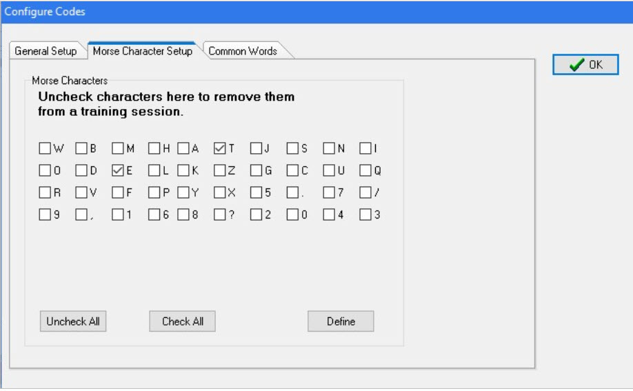
In my net surfing I came across Obi, who makes a range of ATA (Analog Telephone Adaptors) devices and phones. I ordered an Obi, now Polycom Obi202 ATA  (Photo 1) as it has a second phone line port that I plan to use for the fax function on my multi-function printer.

Picture of the Polycom Obi202

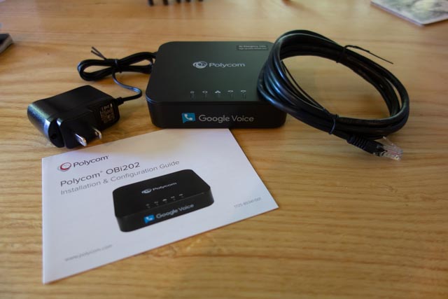
(Photo 1) Polycom Obi202

The back of the unit (Photo 2) has the two phone line (RJ11) connectors, a USB port for future functionality and two RJ45 connectors, one for Internet in and one for Internet out.

Back of the Obi202 showing the connections

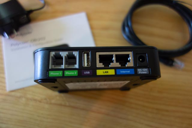
(Photo 2) Back of the unit.

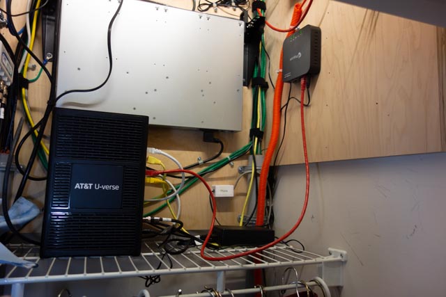
I will be installing the device in my hallway coat/telecom closet (Photo 3).

Photo of the interior of the hallway closet, showing the AT&T fiber modem, and cables and equipement mounted on the walls above the coat rod.

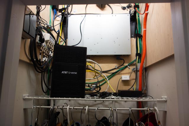
(Photo 3) Telecom closet.

I used a piece of masking tape to make a template for the mounting slots (Photo 4).

A piece of masking tape on the back of the unit with marks on it to indicate were the mounting slots are located.

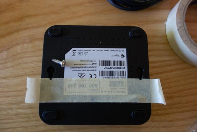
(Photo 4) Marking the mounting slots

I drew a level line with a torpedo level and stuck the tape to the line (Photo 5).

Template tape stuck to backer board following the level pencil line.

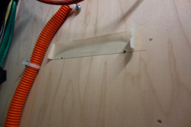
(Photo 5) Tape template and level line

Drilled the holes for the mounting screws (Provide your own) and screwed them in (Photo 6).

Installed mounting screws on the backer board

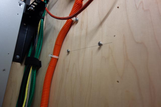
(Photo 6) Installed mounting screws

I connected the provided patch cable to an open Ethernet port on the AT&T modem (Photo 7).

Back of AT&T fiber modem, showing were the patch cable is attached

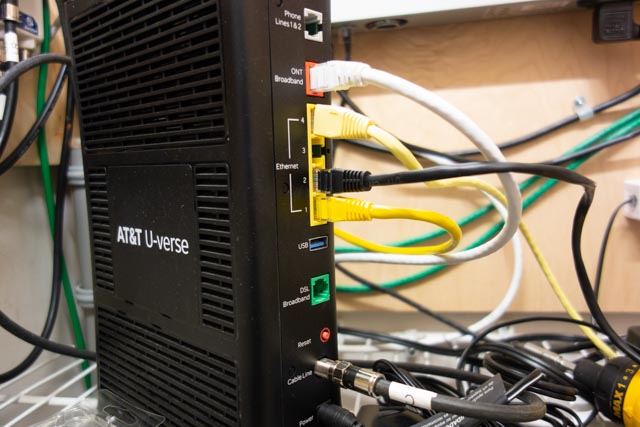
(Photo 7) Modem Ethernet ports.

and to the Internet in port on the device (Photo 8).

Ethernet patch cable connected to the Internet in port on the Obi 202

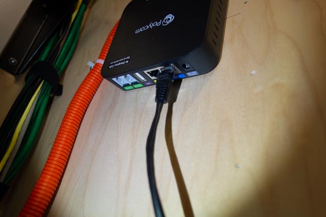
(Photo 8) Patch cable attached to the Obi 202

A four-wire phone cable with RJ11 connectors goes from the Phone 1 port on the unit to a surface mount block in the closet (Photo 9).

Single jack surface mount block with a RJ11 keystone connector with a phone line coming  from the Phone Line 1 port on the device.

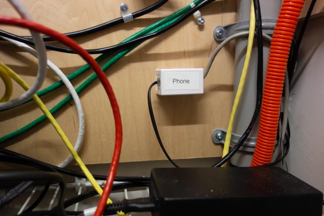
(Photo 9) Telephone line cable connected to the surface mount block.

. The cable from the block is spliced into the house’s original telephone service cabling and provides a dial tone to every telephone outlet in the house.

Before installing the power supply, I mark it with a paint marker to identify what equipment it is used for and the output voltage (Photo 10).

Unit power supply with the purpose and output voltage marked on it.

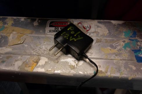
(Photo 10) Power supply

This comes in handy later to match up equipment with a power supply or to clean out a drawer that is overflowing with old power supplies.

The power supply is connected to an open outlet on the server rack PDU (Power Distribution Unit) and to the device. We have power and blinking lights (Photo 11).

Obi 202 connected and powered up

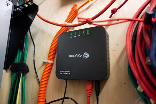
(Photo 10) Connected and powered up.

An Aastra 480e, analog desk phone, is connected to the phone jack in my office. I have a dial tone and I dial the special number provided in the instruction and do a echo test (Photo 11).

Phone sitting on desk

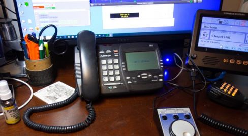
(Photo 11) Desk phone in place.

The next step is to set up a account on Obitalk.com. Once you have done that, you start the setup for a new device. On the phone connected to the ATA, you dial the number provided on the setup page and the Obitalk back end server identifies the device and you will see the device listed on your account web page

With a Obitalk account you can call and talk to other Obitalk accounts for free, but to call outside of the Obitalk network you need to have a account with a VOIP service provider. Obitalk supports most of the major home and small office VOIP providers as well as Google Voice. I have used Google Voice since before the technology was bought by Google and have been satisfied with the service. Best of all it is free for calls in the U.S. and Canada. But if you think that Google already knows too much about your life, you can go with one of the other VOIP providers. Also a big Warning, 9-1-1 service does not work with Google Voice. However you can add 9-1-1 service from another provider to your setup in Obitalk and still use Google Voice. Another concern is what Google gives for free, can be taken away in an instant, so I would not use a free Google Voice account for a phone number that is tightly tied to your business or where you can’t take an outage for a day or two. If you pay for G suite, those worries are about nil as Voice is part of G suite

Since I used my Google account to set up my Obitalk account, it had already configuring the Polycom Obi 202 to work with Google Voice. I made a few selections on what phone line to use for inbound and outbound calls and that was it. Configuration took less than 10 minutes and the total time I spent on the installation was about a hour. Most of that time was bringing in and then putting up the tools I used to install the device in my closet. Voice quality is very good. Reliability is too soon to tell.

Inside of the closet with the completed installation on the right wall

(Photo 12) The finished installation

Bill, N8BR on the OCRA Monday Night 10M Net via Video Conference

Remember the HF phone patch that used to be commonplace in the ham shack years ago?  How about a video conference HF patch?  Or for that matter, flip a switch and it’s a video conference to VHF/UHF patch?

Bill, N8BR does not have an HF station at his QTH, but that did not stop him from listening to the net and Dan, KR4UB passing on his comments to the net.

Dan hosted a video conference and invited Bill to join the OCRA Monday Night 10M Net on 28.450 via video conference.  Ham station audio is fed into the computer running the video conference application. A simple switch of the video conference microphone device driver setting from the normally used Logitech HD camera microphone to the computer line-input brings the ham radio receiver audio and Dan’s Heil headset microphone audio into the video conference.

[c] [y] photo by KR4UB, OCRA Inc

Much of the equipment used and shown below has origin in other usage and has morphed into a small home audio studio serving multiple purposes. This application is a good example of the versatility it can provide.

The video conference “audio patch” application demonstrated here might could be built using some of the audio interfacing devices found in today’s ham shack for computer sound card driven amateur radio communication modes. However, if undertaken getting the audio chain correct might still require use of external audio mixers, attenuators, and additional isolation and perhaps impedance matching transformers, and instrumentation to get the sound right.

W2IHY Technologies Equalizer Function

The ham radio connections in this setup uses a W2IHY Technologies Equalizer that has multiple microphone inputs, one used for the Heil Headset microphone and a second input is used for the video conference inbound audio feed.  The internal microphone amplifier gain is adjustable to ensure appropriate drive level to the selected ham transmitter with the output fed via an internal isolation transformer for RFI protection. The output is switch selectable to one of  two ham station transmitters, in this case a Yaesu 8900 VHF/UHF and the Elecraft K3s transceiver. The phone jack output is an outbound (ham transmitter mic input) audio monitor output that is also connected to one of the Roland Monitors as described below. The equalizer interconnection ports available for all audio outbound to the ham radios are shown below.


Roland CM-30 Studio Monitor Function

Two Roland CM-30 Mini-Cube Studio Monitors in an interconnected stereo link configuration provides multiple audio channel mixer inputs as shown below on the one of the two units. One of the CM-30 units is used for all inbound (video conference incoming audio & ham radio receiver audio) feed mixing. Outbound (ham transmitter microphone inputs & video conference outbound) audio is separately mixed in, permitting audio from all sources to be monitored on the Heil headset as a final control operator quality check. Roland, a major manufacturer of musical instruments and sound stage equipment describes the CM-30 as a multi-purpose portable mixing monitor for the home-studio and portable live monitoring onstage applications.


A Jensen two channel isolation transformer previously used in a home theatre application is used to provide RF & ground loop isolation between the ham station and computer audio connections.  Braid ground strapping bonds all equipment to the common station ground.

A recently added connection for the video conference audio output will permit that feed to be mixed into the Elecraft HF or the Yaesu VHF/UHF mic input so video conference folks have half-duplex two way audio communications and can join the rag chew. None of this will be automatic and will require the control operator to set up the “audio patch” and operate the PTT control, the same as was required by the FCC back in the days of “phone patch” operations.

Inbound, Outbound, Mixing, Attenuators, etc, etc

Does the above discussion of all the inbound, outbound, audio mixing sound like one giant circular loop?  Not surprising… Ever wonder why speakerphones, telephone handsets, cellphones, bluetooth headsets, hearing aids and now video/audio conferencing…. any accoustic environment where speakers and microphones are in close audio proximity doesn’t turn into an enormous squealing audio feed back loop?  You’ve probably heard that many times with public address systems. What’s the magic?  What invention took place and has been deployed in telephone systems from the beginning?  The telephone hybrid transformer, used in bidirectional audio paths where two audio directions are combined in to a single audio channel. This function is essential in today’s world of communication devices and typically done with digitial signal audio processing. The mixing and combining of audio paths described in the above setup had to be done in a way to avoid generating an audio feedback loop at several possible points in the circuit.  The bidirectional processing or half-duplexing of conference audio by a video conference service is also a necessary ingredient.

The Nearby HT / Repeater Echo Effect

You’ve probably have experienced this effect in ham gatherings when you transmit on with your HT into a repeater and someone close to you has their HT volume turned up on the same repeater you are using.  You’ll hear your own voice coming through being delayed in time or an outright audio feed back squeal occurring. The delayed audio echo effect is caused by an audio delay line in the repeater controller for the purpose of removing squelch noise bursts at the beginning and end of every transmission into the repeater and also for masking DTMF repeater control tones sent to the repeater.  The OCRA 442.150mHz repeater is programmed to use a 70 msec audio delay to accomplish the above purposes. Sounds short, but very disorienting to hear your own voice delayed in time as you try to speak!

The conference to repeater audio bridge described in this article can have similar echos in the video conference side when repeater radio transmissions are recirculated from radios in the video conference. Video conferences can be more vulnerable as downloaded video conference applications typically provide a microphone audio AGC (automatic gain control) that if checked will adjust your computer/conference device microphone gain on the fly to make all voices at the same level in the conference. This is a good thing for the conference, but stray radio audio can be problematic.

However, the effect can be totally eliminated by proper audio protocols being practiced by those in the video conference. Those procedures will be described in a separate article.

While the equipment used here may border on overkill, hopefully the above audio discussion explains the necessity and there are advantages especially in the ability to measure, set and monitor audio levels at the key points in the audio chain. Among other uses, this setup has been used for some years as the final over the air audio level checks before a newly built repeater is deployed to a difficult to reach site such as the OCRA 442.150 mHz repeater located high up on the TV tower.

The setup is also used for periodic repeater checks and troubleshooting when repeater problems have arisen. The computer can do extended VOX triggered recording of the repeater to catch intermittent problems and spectrographic analysis software can be helpful on certain types of repeater issues.

Useful Software for Proper Audio Setup

Two computer applications were used to adjust the audio levels for optimum quality. The first program called Spectrogram, used in a vast range of fields, was written many years ago by Richard Horne, an Electrical Engineer working for the U.S. Navy. The second program Goldwave, a professional digital audio application was used to analyze historic recordings of the Moon landing, including establishing the “missing word” from astronaut Neil Armstrong’s famous line.

In summary, the building of this setup has been heavily influenced by other audio interests & needs, but also by experience in building the OCRA repeaters for the last 20 years. Mentoring by Danny, K4ITL in the early days of repeater building taught what it takes to set up repeaters to have excellent audio quality.

Dan, KR4UB

It was the night before Christmas and….

It was the night before Christmas and ….

Oh, No, No, No!!!!

It was Saturday morning before Christmas, 2019, and seven local hams were gathered at the rear round table of Virlie’s Grill, Pittsboro, NC. Just the week before, John Mitchell, KK4VUR had distributed early Christmas gifts of nice surplus utility enclosures. BIG THANKS to John, KK4VUR !

As part of the lively discussion this morning, Herb Allred, N4HA, revealed what he has already done with his utility box. Attached are photos of his “to go” station, with carrying handle attached to the top, containing his 20 meter CW QRP transceiver, antenna wire, iambic paddle, headphones and battery pack. The first photo shows Herb Alred, N4HA, on the left and Jim Davis, W4CFO, on the right. Note the use of popsicle sticks to secure the key paddle inside the lid of the box.

Very creative and ready to put on the air, maybe at a state park. Add a sandwich, drink and a few snacks in the box, (note the ketchup and maple syrup in the photo), and he is in for a good time.

Good luck Herb with many contacts and some DX. 20 meters has been better lately.

Don’t forget, Saturday mornings, 8:30 am (or earlier) at Virlie’s Grill, Pittsboro, NC (round table in the back of the room).

Best 73 and very MERRY CHRISTMAS to all and HAPPY NEW YEAR !

John, KX4P

Morse Code Classes via a UHF Repeater… starting January 8th

Steve Jackson, KZ1X

revised December 29 2019 ….

The way that most people learn Morse Code best is in a classroom style setting. From roughly 1840 through about 1970, this was the manner in which most people learned Morse Code.

For a variety of reasons, beginning in the early 1980s, a trend began where people either did not have the opportunity to attend a classroom setting and / or took it upon themselves to try and self-teach the skill. The former is unfortunate; the latter, many times more challenging.

Well, amateur radio certainly has changed in the ensuing decades but what has not changed is the desire among many hams to be able to use Morse Code on the air.

Due to practical limitations such as the lack of a suitable classroom venue, the geographically diverse nature of potential students, busy lifestyles, and availability of instructors, it is not likely we will see a return to regularly scheduled, local, sit-down type Morse Code classes.

However, for those who do wish to learn in a class-styled environment, and who already hold a Technician or higher grade of amateur license, there may still be an alternative for a group-oriented Morse Code learning environment.

A Proposal

OCRA maintains a wide coverage UHF repeater. Like the majority of repeaters over the past 15 years or so, it is inactive most of the time.

This terrific and underutilized resource could easily host a scheduled on-the-air Morse Code class for students already holding amateur licenses. This document describes such a class.

Conceptually, the idea is simply to move a traditional sit-down classroom experience to one conducted in real time via a repeater. By making it interactive, on the repeater, the class will train participants to communicate over-the-air in Morse Code.

Yes, that’s it. The sole goal of the class is conferring the demonstrable ability to send and receive Morse Code on the air.

Before you ask:

There is no sending or receiving speed goal for this class.

Setting such a goal was important in an era when there was a standardized FCC test to pass. Teaching to receive at a given speed did not serve students well; it only helped the test proctors. Moreover, without a sending test, the underlying Morse communications skill of the student is not certain.

Therefore, a fixed-speed goal is not appropriate for a Morse Code class taught in 2020. Think of this class instead like “Marconi meets Montessori.”

Anticipating your next question:

What speed are the lessons sent at?

The answer is:

Since the class goal is to be able to make practical use of Morse Code on the air, the so-called speed for lessons is actually a more complicated issue than a simple number.

The speed of the dots and dashes for lessons is set at the natural rhythm rate, such the listening part of the brain will not try to ‘count’ these symbols. Instead, each letter’s acoustic pattern gets interpreted by the brain as a unique musical sound. Thus, the same part of the brain used to remember the first notes of a favorite song is activated to memorize the letters.

This is also why significant effort has been put into making the tones used in the class have musical integrity (pitch, tonality, and harmonic content are controlled).

In turn, the space between the letters is artificially lengthened from the expected spacing, so that the student will have time to write down each letter sent.

Focusing on “how fast?” as the sole metric for success is great for horses, not for people. This is about recognition, not rate. Once one knows all the letters and digits, increased speed is then only a function of experience and desire.

How Will The Class Work?

A class participant will learn Morse code over a period of approximately two months. The letters of the alphabet, the ten digits, and certain punctuation and procedural signals are introduced to students each week, in a graduated process.

Materials used are a combination of a Windows software application by G4FON, the K1EL Morse Tutor keyer kits, and a weekly over-the-air interactive instructor-led lesson. The software is used to make the letter introductions, and to help weekly home practice.

Dividing the 26 letters into four groups allows one to learn the more frequently used letters first. In turn, this allows the most rapid progress towards forming words. Quickly thereafter, students can create simple sentences.

The class design is interactive because student participants both receive and send in each class, and draw upon each other’s success. All of this occurs exactly as it would in a ‘live’ in-person setting. It is therefore vitally important that the students faithfully complete each week’s homework and come prepared for the next class.

Classes, Equipment, and Software

Classes

The class itself consists of eight on-the-air lessons,  plus preparatory work.

Preparatory work consists of using the software to practice and learn the assigned new letters each week. Most people find that this will take from 1 to 3 hours per week. (Weeks 2 and 4 are hardest.)

Each on-the-air lesson will be roughly 30-45 minutes in length.

There is a fixed curriculum. One cannot ‘skip’ any lesson, nor are there any make-up lessons possible.

This is in part because the lessons are not simply recordings. They are interactive, and, each lesson builds upon the previous one. In addition, students are active participants in the learning process for and with other members of their cohort.

Each over-the-air lesson consists of a student-listening portion, and a student-sending portion.

  • In the student-listening portion of each class, the instructor reviews the new letters introduced the previous week, by sending the letters over the air to the students.

This listening portion consists of these most recent letters, sent in three sequences of ten random groups of four letters each. The instructor, using an automated tool, transmits these.

After the lesson, the actual letter groups sent will be posted on line, so students can check their copy.

  • In the student-sending portion, the student will formulate words from all the letters learned so far in the class, and then send those words over the air so other class participants can copy them. Each student will send at least two words (generally 4 or 5 letters each).

The student-sending portion of the class is one reason for the K1EL Morse Code tutor kits. These kits allow a low-cost way of sending good quality modulated-CW signals over the repeater.

If a student wishes to use some other Morse tone generation gear, that is their option. However, it will still be necessary to use the same settings as shown below (in the software topic), so that all class participants’ signals sound similar (pitch, speed, spacing).

The student will need to be able to hold their microphone close enough to their kit’s speaker so they can send their words over the air. Of course – they must ALSO access the repeater well while doing so.

Equipment

The intention is for the typical local, licensed amateur to participate in the class easily, with minimal additional expense.

An assumption is that all students will already have the means to access the repeater, often via a handheld radio. It is prudent to check one’s signal into the repeater from the location where one will participate in each week’s lesson, prior to starting the course. Adding an external gain antenna and perhaps a corded microphone accessory could be very helpful.

An in-person set-up session prior to the first class will be available, so that students’ K1EL Morse Tutor kits can be programmed. The reason for this is because the Morse Tutor kits are programmed using Morse Code, and of course, the student using this Tutor does not yet know Morse Code.

The programming will be for rates, student callsign, audio pitch, and related settings.

Software

The software used for the class is by G4FON. It is a Windows program. (If you absolutely must use some other platform, please contact Steve, KZ1X, to discuss options.)

Several features of this software make it the ideal choice. The primary one is the feature where the user can select specific letters for the computer to send, repeatedly, allowing the student to learn new letters every week according to the class syllabus.

Other G4FON program options allow the computer-generated Morse Code to ‘sound’ like the class lessons do.

To set up the G4FON software for the class, choose the following settings on the main screen:

  • Set the Pitch to 660
  • Actual Character Speed to 15
  • Effective Code Speed to 5

and make any needed changes to the ‘button’ type options, as shown above.

Afterwards, open the ‘Setup’ tool and choose the “Morse Character Setup” tab:

For the first lesson, choose only the letters ‘T’ and ‘E’ as shown above.

For the second lesson, choose only the letters ‘E’ ‘I’ ‘S’ ‘H’ ‘T’ ‘M’ and ‘O.’

See below for the subsequent week letter introductions.

Here is a link to access the software:

http://www.g4fon.net/CW%20Trainer.htm

Lessons

Lesson 1 E T

Lesson 2 E I S H T M O

Lesson 3 A W J N D B

Lesson 4 U V G Z K R P X

Lesson 5 F C L Q Y

Lesson 6 1 2 3 4 5

Lesson 7 6 7 8 9 0

Lesson 8 . , ? /