Remember the HF phone patch that used to be commonplace in the ham shack years ago? How about a video conference HF patch? Or for that matter, flip a switch and it’s a video conference to VHF/UHF patch?
Bill, N8BR does not have an HF station at his QTH, but that did not stop him from listening to the net and Dan, KR4UB passing on his comments to the net.
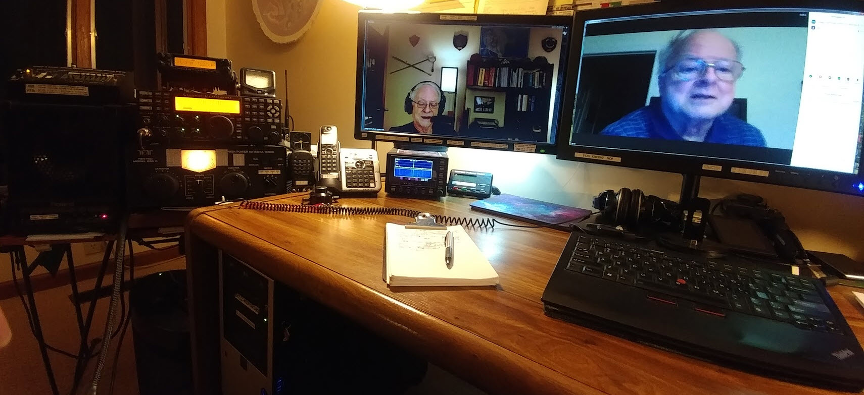
Dan hosted a video conference and invited Bill to join the OCRA Monday Night 10M Net on 28.450 via video conference. Ham station audio is fed into the computer running the video conference application. A simple switch of the video conference microphone device driver setting from the normally used Logitech HD camera microphone to the computer line-input brings the ham radio receiver audio and Dan’s Heil headset microphone audio into the video conference.
[c] [y] photo by KR4UB, OCRA Inc
Much of the equipment used and shown below has origin in other usage and has morphed into a small home audio studio serving multiple purposes. This application is a good example of the versatility it can provide.
The video conference “audio patch” application demonstrated here might could be built using some of the audio interfacing devices found in today’s ham shack for computer sound card driven amateur radio communication modes. However, if undertaken getting the audio chain correct might still require use of external audio mixers, attenuators, and additional isolation and perhaps impedance matching transformers, and instrumentation to get the sound right.
W2IHY Technologies Equalizer Function
The ham radio connections in this setup uses a W2IHY Technologies Equalizer that has multiple microphone inputs, one used for the Heil Headset microphone and a second input is used for the video conference inbound audio feed. The internal microphone amplifier gain is adjustable to ensure appropriate drive level to the selected ham transmitter with the output fed via an internal isolation transformer for RFI protection. The output is switch selectable to one of two ham station transmitters, in this case a Yaesu 8900 VHF/UHF and the Elecraft K3s transceiver. The phone jack output is an outbound (ham transmitter mic input) audio monitor output that is also connected to one of the Roland Monitors as described below. The equalizer interconnection ports available for all audio outbound to the ham radios are shown below.
Roland CM-30 Studio Monitor Function
Two Roland CM-30 Mini-Cube Studio Monitors in an interconnected stereo link configuration provides multiple audio channel mixer inputs as shown below on the one of the two units. One of the CM-30 units is used for all inbound (video conference incoming audio & ham radio receiver audio) feed mixing. Outbound (ham transmitter microphone inputs & video conference outbound) audio is separately mixed in, permitting audio from all sources to be monitored on the Heil headset as a final control operator quality check. Roland, a major manufacturer of musical instruments and sound stage equipment describes the CM-30 as a multi-purpose portable mixing monitor for the home-studio and portable live monitoring onstage applications.
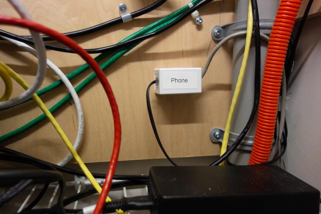
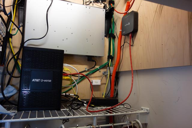
A Jensen two channel isolation transformer previously used in a home theatre application is used to provide RF & ground loop isolation between the ham station and computer audio connections. Braid ground strapping bonds all equipment to the common station ground.
A recently added connection for the video conference audio output will permit that feed to be mixed into the Elecraft HF or the Yaesu VHF/UHF mic input so video conference folks have half-duplex two way audio communications and can join the rag chew. None of this will be automatic and will require the control operator to set up the “audio patch” and operate the PTT control, the same as was required by the FCC back in the days of “phone patch” operations.
Inbound, Outbound, Mixing, Attenuators, etc, etc
Does the above discussion of all the inbound, outbound, audio mixing sound like one giant circular loop? Not surprising… Ever wonder why speakerphones, telephone handsets, cellphones, bluetooth headsets, hearing aids and now video/audio conferencing…. any accoustic environment where speakers and microphones are in close audio proximity doesn’t turn into an enormous squealing audio feed back loop? You’ve probably heard that many times with public address systems. What’s the magic? What invention took place and has been deployed in telephone systems from the beginning? The telephone hybrid transformer, used in bidirectional audio paths where two audio directions are combined in to a single audio channel. This function is essential in today’s world of communication devices and typically done with digitial signal audio processing. The mixing and combining of audio paths described in the above setup had to be done in a way to avoid generating an audio feedback loop at several possible points in the circuit. The bidirectional processing or half-duplexing of conference audio by a video conference service is also a necessary ingredient.
The Nearby HT / Repeater Echo Effect
You’ve probably have experienced this effect in ham gatherings when you transmit on with your HT into a repeater and someone close to you has their HT volume turned up on the same repeater you are using. You’ll hear your own voice coming through being delayed in time or an outright audio feed back squeal occurring. The delayed audio echo effect is caused by an audio delay line in the repeater controller for the purpose of removing squelch noise bursts at the beginning and end of every transmission into the repeater and also for masking DTMF repeater control tones sent to the repeater. The OCRA 442.150mHz repeater is programmed to use a 70 msec audio delay to accomplish the above purposes. Sounds short, but very disorienting to hear your own voice delayed in time as you try to speak!
The conference to repeater audio bridge described in this article can have similar echos in the video conference side when repeater radio transmissions are recirculated from radios in the video conference. Video conferences can be more vulnerable as downloaded video conference applications typically provide a microphone audio AGC (automatic gain control) that if checked will adjust your computer/conference device microphone gain on the fly to make all voices at the same level in the conference. This is a good thing for the conference, but stray radio audio can be problematic.
However, the effect can be totally eliminated by proper audio protocols being practiced by those in the video conference. Those procedures will be described in a separate article.
While the equipment used here may border on overkill, hopefully the above audio discussion explains the necessity and there are advantages especially in the ability to measure, set and monitor audio levels at the key points in the audio chain. Among other uses, this setup has been used for some years as the final over the air audio level checks before a newly built repeater is deployed to a difficult to reach site such as the OCRA 442.150 mHz repeater located high up on the TV tower.
The setup is also used for periodic repeater checks and troubleshooting when repeater problems have arisen. The computer can do extended VOX triggered recording of the repeater to catch intermittent problems and spectrographic analysis software can be helpful on certain types of repeater issues.
Useful Software for Proper Audio Setup
Two computer applications were used to adjust the audio levels for optimum quality. The first program called Spectrogram, used in a vast range of fields, was written many years ago by Richard Horne, an Electrical Engineer working for the U.S. Navy. The second program Goldwave, a professional digital audio application was used to analyze historic recordings of the Moon landing, including establishing the “missing word” from astronaut Neil Armstrong’s famous line.
In summary, the building of this setup has been heavily influenced by other audio interests & needs, but also by experience in building the OCRA repeaters for the last 20 years. Mentoring by Danny, K4ITL in the early days of repeater building taught what it takes to set up repeaters to have excellent audio quality.
Dan, KR4UB