Original post date April 2021 by KR4UB
After viewing a recent Youtube video posted by the American Radio Relay League, Inc ARRL youtube video regarding RF noise that can be generated by inverter based generators, I decided to do some testing of my inverter generator, a later model, slightly higher capacity unit compared to a Honda generator in the ARRL youtube video.
First Impressions
The RF noise characteristics of my eu2200i unit do not seem as pronounced as demonstrated in the ARRL video, although that could be due to test configuration differences. It was noticed in the video that their antenna was very low and close to the generators. The horizontal loop and dipole antennas at home used in this testing are at an approximate 55 foot height over the test area.
- The only amateur band that had generator noise was 80 meters and was loud enough to be an issue for Field Day.
- Reducing the generator load helps reduce radiated RF noise.
- Using a shorter drop cord can help, but not enough to eliminate generator inverter radiated noise.
Line Filter Project
Given the club’s Field Day plans to run in a higher RF power output class with the associated higher battery draw, the two transmitters of the combined 10m/6m stations I help set up and operate will be especially demanding on the batteries. If the Honda inverter generator is to be used to recharge this station’s batteries, a fix is needed to eliminate the possibility of RF interference to nearby field day stations.
The first step of the project began with a conversation with Howie, WA4PSC ProAudio Engineering who stocks the Fair-Rite toroid cores, regarding the best choice of ferrite toroids. His recommendation was the Fair-Rite 4.0” OD x 1″ H mix 31 units, given the frequency range at issue and will permit larger spacing between turns for less capacitive coupling.
The test configuration consists of the Honda inverter generator, drop cord and the power load placed beneath my HF horizontal loop antenna located approximately 55’ overhead. It was also in the vicinity of a dipole antenna also at 55’ above ground. Noise was observed on an Elecraft K3s and a SDRPlay 1a SDR receiver both using the same antenna. All displays of received noise below are from the SDRPlay 1a SDRuno application.
The generator test load is a 1500 watt electric heater, connected to the generator by a 50’ long drop cord. Several orientations of the drop cord were tried and as expected, there is an observable difference in received radiated noise based on drop cord orientation.
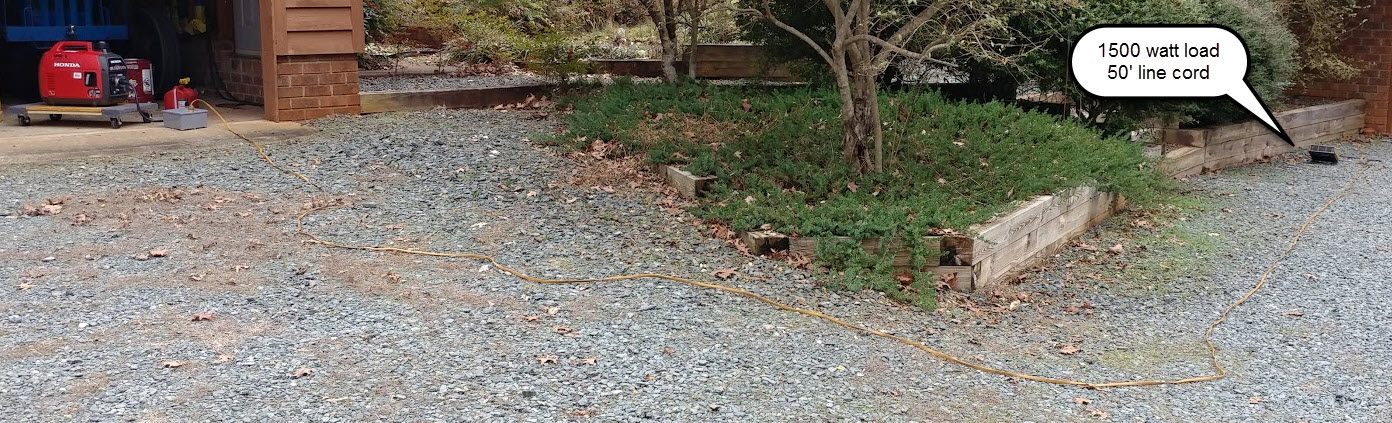
photo by KR4UB, © OCRA Inc
Two filter configurations were tested using different toroid winding configurations, both using three of the Fair-Rite 4″ OD x 3″ ID x 1″ L 2631814002 toroids.
Toroid Configuration #1
Not knowing whether the preponderance of the Honda inverter generator noise was common mode or differential mode, the first test was with toroid #1 wound with both neutral and the hot lead in a common mode attenuation configuration and then toroids #2 & #3 used as follows. Toroid #2 was for neutral & ground, wound for differential mode attenuation and toroid #3 for the hot lead similarly wound for differential mode attenuation. This configuration was not very effective in reducing the observed noise.
Toroid Configuration #2
Not satisfied with the above result, the toroids were all rewound for common mode attenuation as shown below:
The hot and neutral lines are wound on two toroids “in series” and the ground wire which can also be driven by common mode noise is on a separate toroid.
The “missing” (or more widely spaced turns you see in the photo below (at the top & bottom of each toroid) were required for these 4″ OD toroids to fit in the 4″ deep box and permit the cover to go back on. As shown the larger 4” OD toroids permit wider spacing between the turns and thus reduce capacitive through coupling across the turns.
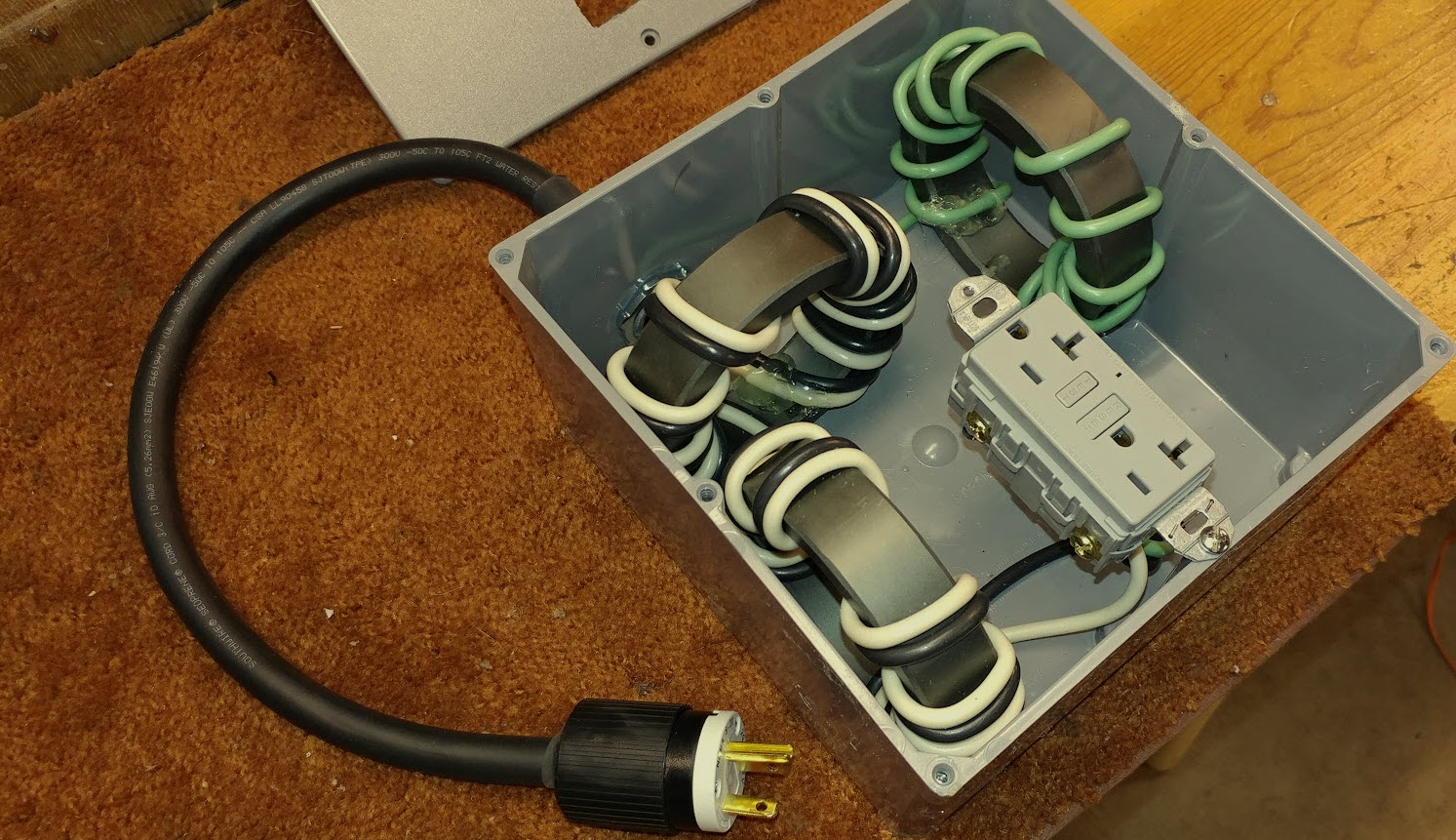
photo by KR4UB, © OCRA Inc
One detail on the unfinished design above will be to bring out a ground wire stud for connection to a ground rod to be located near the generator.
RF Noise Test Results
Using a real world 80m antenna as the test reference for radiated RF generator noise is not ideal in determining any absolute noise level reduction by the filter given the typical high 80M noise floor. But it does reflect the real world of a typical Field Day station setup.
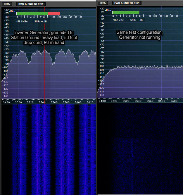
The unfiltered RF noise of the generator driving a 1500 watt load via a 50’ drop cord is shown below in the bandscope display of my SDR receiver connected to the horizontal loop antenna. The display shows the frequencies (the repeating blue bands) and correlating waves of increased noise across the noise floor of the 80m band. Using AM detector mode, the noise is audibly loud; however in LSB detection mode the noise is not audibly loud, just a higher background impulse type sound. While there were some signals on the band, only one (the orange line) was strong enough to show above the elevated noise floor.
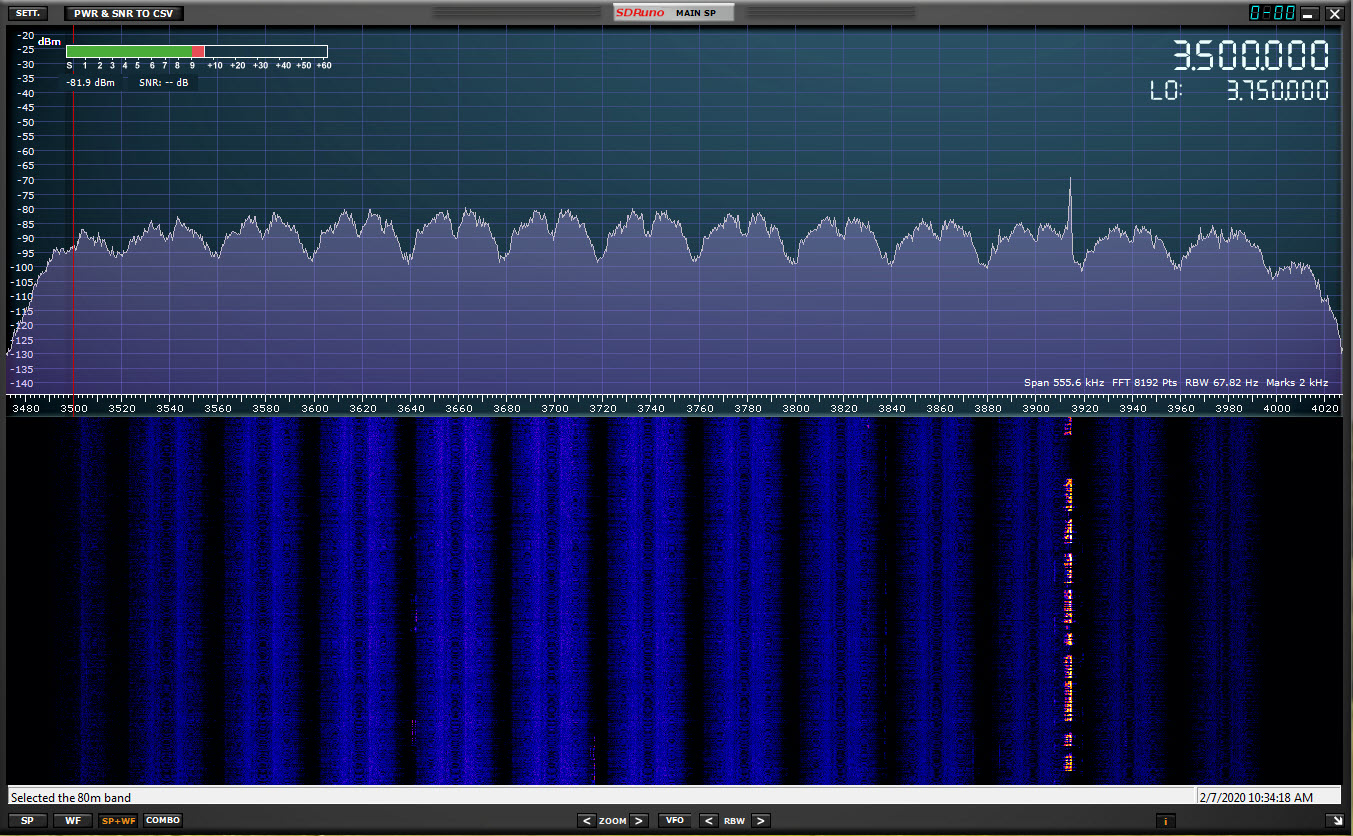
photo by KR4UB, © OCRA Inc
Below is a sweep of the ambient 80m noise level without the generator running and, ironically during a widespread AC power outage that occurred February 07, 2020. The amateur radio station is powered directly by a large battery bank and the computer for this testing is on a high quality (and very low generated noise) UPS designed for the commercial market sector.
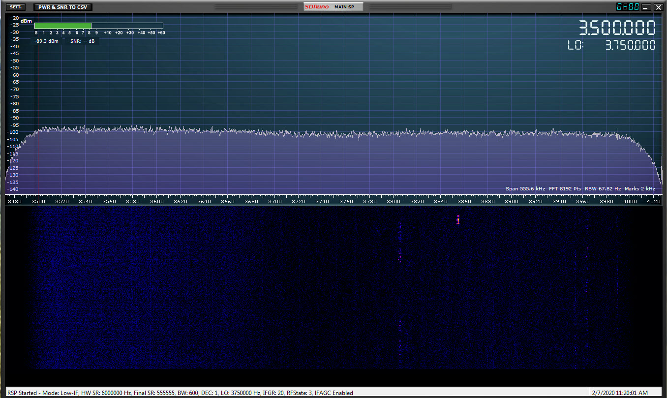
photo by KR4UB, © OCRA Inc
To illustrate the effect of generator load or lack of, on radiated noise, the 80m radiated noise shown below is with the same configuration as the first chart, i.e. the 50 foot cord attached, no filter, and no electrical load on the generator.
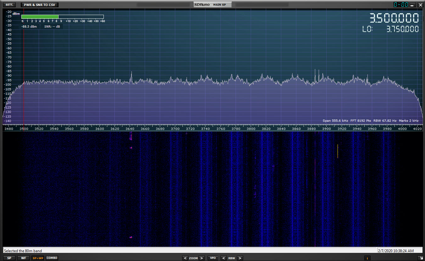
photo by KR4UB, © OCRA Inc
Finally, the noise filter effectiveness of Toroid Configuration #2 is shown below. The measurement below is with the same 1500 watt load, connected through the 50 foot drop cord, but with the filter inserted at the generator as shown on the next page. Compared to the first chart with no filtering, none of the repeating blue bands and correlating waves of increased noise are present across the 80m spectrum. No interference was found on the 40m – 10m ham bands or adjacent frequency bands. The multi colored traces are 80m stations active during the measurement.
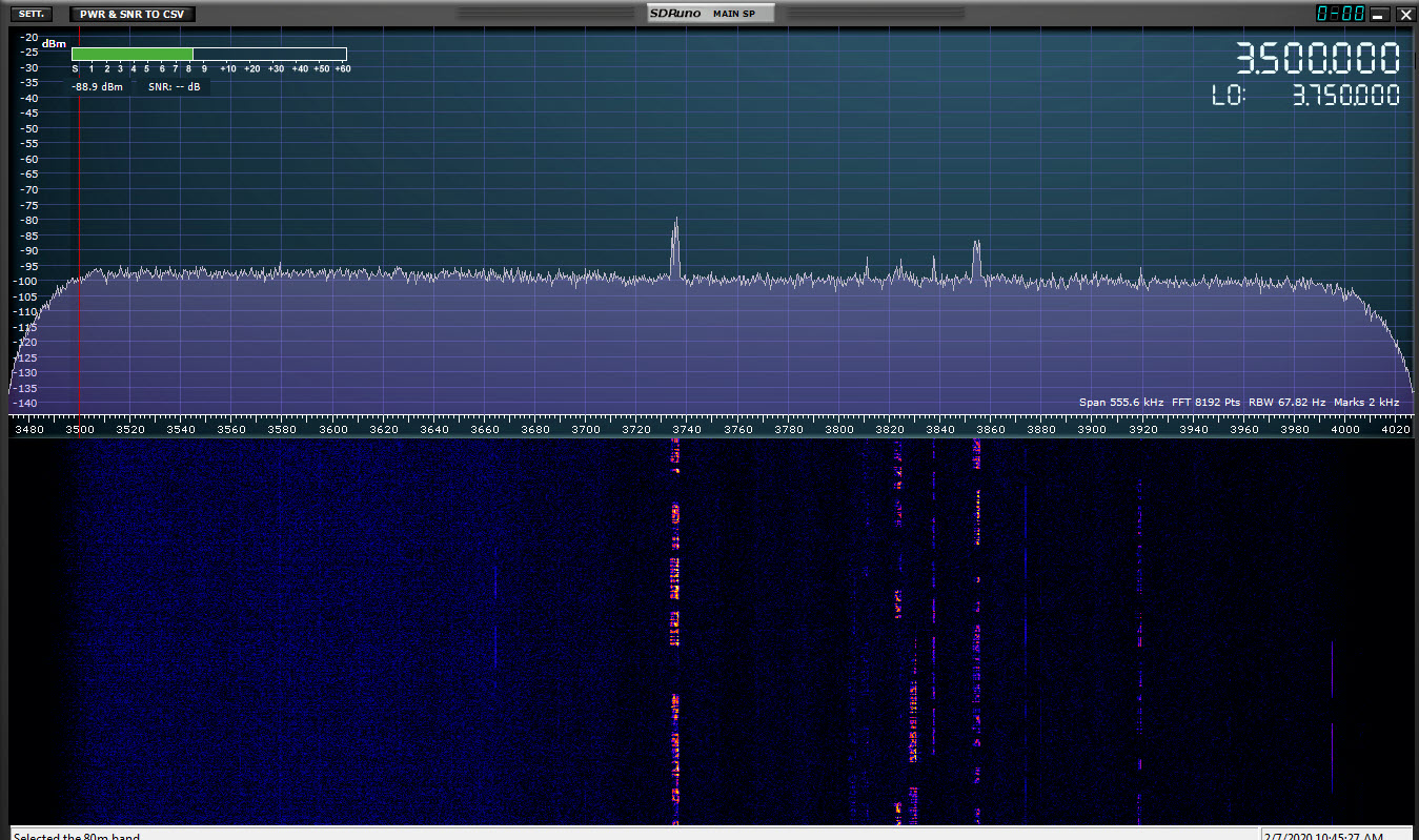
photo by KR4UB, © OCRA Inc
Throughout the test, care was taken to keep all connected equipment and the drop cord in the same physical configuration. Earlier testing showed drop cord orientation (and of course length) can make a considerable difference in results.
Filter at the grounded generator & 50 foot cord connecting the 1500 watt load
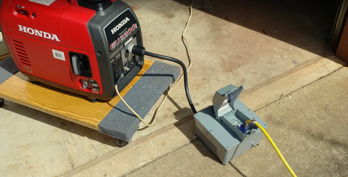
photo by KR4UB, © OCRA Inc
Final filter design
Below is the final design using toroid configuration #2, with a GFCI outlet and stud bolt connection for ground included. The stud bolt ground is connected to the GFCI electrical outlet ground and goes to the generator electrical outlet via the plug connected cable green wire. Per Honda documentation the outlet ground is internally connected to the generator frame components.
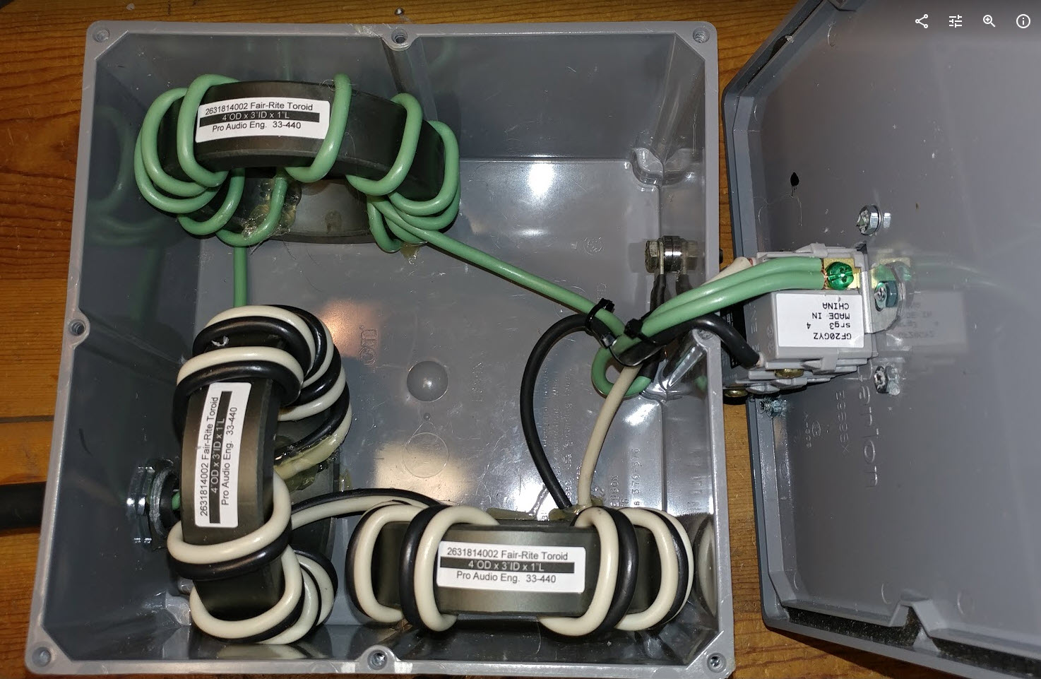
photo by KR4UB, © OCRA Inc
While test results show this filter to provide effective RF noise reduction with the Honda eu2200i inverter generator, other similar style inverter generators may present a different situation due to possible different power transistor technology and inverter switching rise times.
PostScriptA postscript is an afterthought, thought of occurring after the letter has been written and signed.In discussing this filter with a few folks the conversation tends to turn to why this or why not that. The first EMI solution that works may be expensive and may not be the only design solution. Such is the world of EMI. The filter I built works, but with the included GFCI and other parts, is a bit pricey, approaching $140.00. Would the smaller less expensive 2.4″ OD ferrites do the job? Testing of a filter using 3 of the 2.4″ OD cores proved the smaller cores to be ineffective. This is most likely from capacitive coupling of the closer wire turn spacing forced by the smaller diameter cores, or perhaps the core cross sectional area yields a magnetic flux path just too small for the amount of RF energy to be absorbed at the lower HF frequencies. Perhaps using only two 4″ OD toroids (eliminating the separate green wire ground toroid) might work, but hasn’t been tested.
Time spent learning what others have learned is always a worthwhile endeavor. Howie, WA4PSC of ProAudio Engineering also passed on some excellent references for further reading. Jim Brown K9YC’s 60 years in ham radio, vice chair of AES Standards Committee working group on EMC and extensive research in the pro audio world is an excellent reference source. Jim’s 59 page “summary” reference document is well worth spending the time on the details of rf filter design. The filter design in this article correllates well with information his document regarding filters for the lower HF bands; e.g.two cores “in series”… check! … seven or more turns per mix 31 core… check! and choking the green wire ground… check, no out of sequence turns on the core… check! Jim’s other publications can be found here.
46 SDR frequency sweeps, involving a number of test configurations, variation in filter components & design and involving considerable time were performed on this project looking for a better magic bullet. It did confirm the filter design in this article performed superbly over a number of test configurations, but no magic bullets were found.