
The repeater reach-ability testing during several recent OCRA Auxcomm nets on the 442.150 repeater and the demo presentation at the April 10 OCRA meeting (see Youtube video) illustrates many examples of how the topography from your location to a repeater site greatly affects the ability to communicate.
Without quantitative tools to analyze the issue, it can be a difficult decision on how to fix the problem. What is the problem? What will be the most effective fix?
Repeater topographic coverage maps can help answer questions specific to your location.
To take advantage of these maps you will need to do 2 things:
- Download and install the Google Maps application from this URL: https://www.google.com/earth/versions/#earth-pro
- Download the Tri-County Repeater Coverage maps located on the OCRA -DFMA groups.io file storage area.
The URL link below contains repeater coverage topographic mapping for the 442.150, 145.450, 147.225 and 145.230 repeaters. More repeaters will be added in the future.
Three maps are available for each repeater to show coverage that can be expected with the typical HT, Mobile or Fixed base (home) installations.
Downloading the Repeater Coverage Maps:
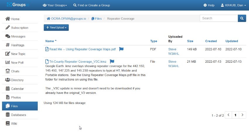
You need to use your OCRA-DFMA groups.io login ID and password to access the files area shown below.
Click on this URL https://groups.io/g/OCRA-DFMA/files/Repeater%20Coverage to go to the file storage area.
When you click on the “Tri-County Repeater Coverage_V3C.kmz” file link as shown below, the file will download onto your computer, per your browser’s download settings.
Using the Google Earth Pro Application:
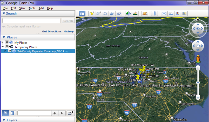
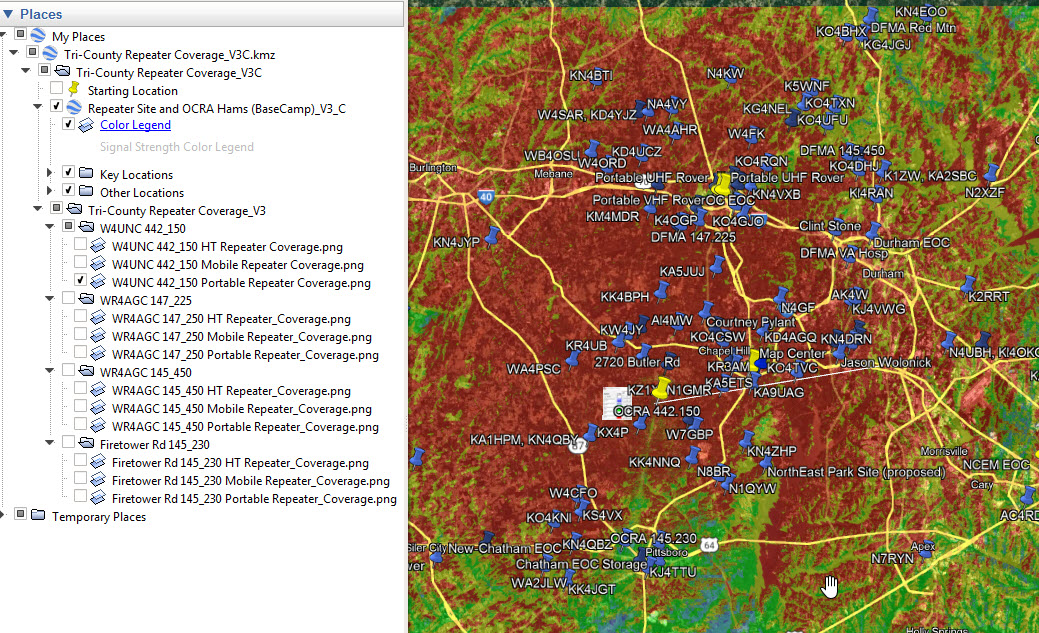
Click on the Tri-County Repeater Coverage_V3C.kmz file to open it with the Google Earth Pro application.
Several Google Earth features need to be active so you can select the coverage maps available for the repeater of interest.
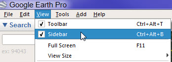
The sidebar on the left will be needed to navigate the maps. If not visible, click on the command line “View, Toolbar” to turn it on.
Click the caret symbol ![]() to expand the settings and the sub-directories within the .kmz file.
to expand the settings and the sub-directories within the .kmz file.
You will want to turn on certain overlays by placing check marks for the applicable blocks as indicated below.
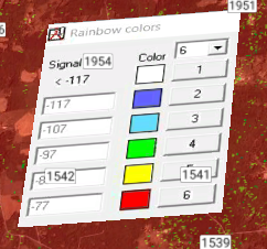
![]() for the “Color Legend” (indicating signal strength into the repeater; more on this later.
for the “Color Legend” (indicating signal strength into the repeater; more on this later.
![]()
![]() “Key Locations” and “Other Locations” will show the repeaters and QTH locations for over 100 hams in the area.
“Key Locations” and “Other Locations” will show the repeaters and QTH locations for over 100 hams in the area.
Place a check mark next to the repeater map and station type of interest. In this example, the check mark is for the 442.150 repeater being used by a portable/home station.
Only 1 repeater map/station type should be turned on at a time.
Note:
- A portable station is one that could be set up for emergency communications and is equivalent to a home station using a 30-50 watt mobile radio, and a small tower or building mounted fixed base antenna up 20 feet off the ground.
- The 147.250 file name below is a typo. It is the 147.225 DFMA repeater.
The maps for our region, created with Radio Mobile – RF propagation simulation software , shows the significant role terrain blocking plays in repeater coverage in our in our area. The color indicated at the selected station’s location indicates the expected signal strength back into the repeater.
- Red (-77dBm strength back to the repeater) is solid copy, no noise or fading communications)
- Yellow (-87dBm), Green (-97dBm) Good communications, may have some occasional noise down in the green areas
- Turquiose (-107dBm), Blue (-117dBm) Will be unpredictable. May work at times reasonably OK with noise & dropouts or not at all.
- White (on the color legend) (-117dBm) No communications. These areas will simply the Google Earth imaging without any coloring.
Common radio setups used for repeater communications are the basis for the 3 topographic map runs made for each repeater.
- 5 watt HT with the standard rubber duck antenna
- Vehicle with a mobile radio with 30 UHF, 50 watts UHF output and vehicle antenna
- Fixed based installation using a mobile radio and a base station antenna higher off the ground.
Additional Information:
Knowing the Effective Radiated Power (ERP) that your radio setup is providing back into the repeater can provide a more tangible perspective.
- The ERP Calculator results below reveals a little better the actual radiated power levels than just considering the antenna gain expressed in decibels.
-
HT 5 Watts with standard rubber duck antenna loss (VHF -6dBi, UHF -3dBi)
- VHF 5W ERP 0.766 watts
- UHF 5W ERP 1.53 watts
-
Vehicle radio and external mounted antenna (e.g. Comet SBB14 VHF 3.5dBi UHF 6.0dBi gain)
- VHF 5W ERP 6.83 watts
- UHF 5W ERP 12.14 watts
- VHF 50W ERP 68.25 watts
- UHF 30W ERP 72.82 watts
-
Fixed based installation again using a mobile radio and fixed base antenna (e.g. Comet GP-9N VHF 8.5dbi UHF 11.9dBi gain)
- VHF 5W ERP 21.58 watts
- UHF 5W ERP 47.22 watts
- VHF 50W ERP 215.84watts,
- UHF 30W ERP 283.32 watts
Coax loss with also have to be considered for the vehicle and fixed based antennas.
I wish to express my thanks and gratitude to Steve, W3AHL for sharing his valuable knowledge and experience with the Radio Mobile RF propagation application.
Dan, KR4UB